background image

13

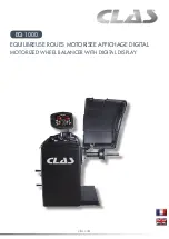
 EQ  1000 

 EQUILIBREUSE ROUES MOTORISEE AFFICHAGE DIGITAL 

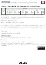
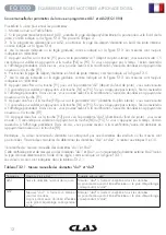
2ème méthode : saisie des diamètres "da1" et "da2" à partir du diamètre nominal

Cette deuxième méthode combine l’utilisation du diamètre nominal de la jante et des corrections indiquées dans 

le tableau T3.2.2.

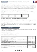
Tableau T3.2.2. Déterminer les diamètres "da1" et "da2" à partir du diamètre nominal 

Programme

Diamètre interne "da1"

Diamètre externe "da2"

ALS1

Da1 = diamètre nominal de la jante 

Da2 = diamètre nominal – 2.0 inches (ou 50 mm)

ALS2

Da1 = diamètre nominal – 1.0 inch (ou 25 mm)

Da2 = diamètre nominal – 2.0 inches (ou 50 mm)

Cette méthode ne requérant pas de prise de mesure manuelle, elle est plus rapide. Cependant, les résultats 

peuvent être légèrement moins précis.

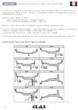
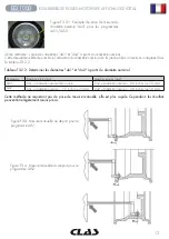
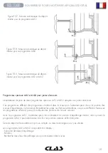
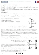
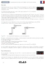
Figure F3.3.1. Exemple de prise de mesure du 

diamètre externe "da2" pour les programmes 

ALS1/ALS2

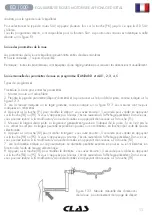
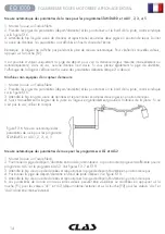
Figure F3.4. Mesure manuelle du déport pour le 

programme ALS1

Figure F3.4. Mesure manuelle du déport pour le 

programme ALS2

Содержание EQ 1000

Страница 1: ...clas com EQUILIBREUSE ROUES MOTORISEE AFFICHAGE DIGITAL MOTORIZED WHEEL BALANCER WITH DIGITAL DISPLAY EQ 1000 ...

Страница 2: ...agnostics 6 Utilisation de la machine 7 Calibration 18 Optimisation 22 Programme masse cachée derrière les batons 24 Deuxième opérateur 26 Programmes de configuration 27 Mode service 30 Différentes alertes 34 Dépannage 36 Entretien 37 Démolition de la machine 37 Informations environnementales 37 Extincteurs 38 ...

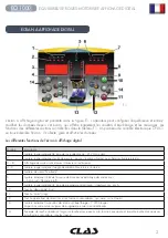
Страница 3: ...iquant l unité de mesure pouces lumière allumée ou millimètres lumière éteinte 3 8 Affichage des valeurs de masses intérieures et extérieures 4 9 Lumière rouge indiquant l angle de déséquilibre interne externe 5 Lumière de statut En attente 6 Lumière indiquant l état de la saisie de données automatique des dimensions Activé on Désactivé off 7 Lumière rouge indiquant le type de programme sélectionn...

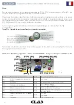
Страница 4: ...e et secondaire Pour accéder à la fonction secondaire d une touche appuyez simultanément sur la touche P7 et sur la touche désirée puis relâchez les deux touches Tableau T1a Paramètres programmes et menus du mode SERVICE Appuyez sur F P3 pour accéder au mode Touche Paramètre programme ou menu Touche Paramètre programme ou menu P1 MENU Programme de calibration du capteur F P1 Non utilisé P2 Non uti...

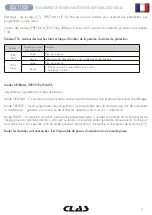
Страница 5: ...en cours La rotation s arrête Modes NORMAL SERVICE et PAUSE L équilibreuse possède trois modes opératoires Mode NORMAL Ce mode est activé lors de la mise en marche de la machine et permet de réaliser l équilibrage Mode SERVICE Divers programmes de configuration sont disponibles dans le mode service afin de paramétrer la machine ex grammes ou ounces ou de vérifier les opérations en cours ex calibra...

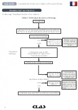
Страница 6: ...Allumage de toutes les LEDs Déclenchement du signal sonore Pause de deux secondes Arrêt de tous les chargements électriques L équilibreuse est elle calibrée NON OUI Calibration roues AUTO SUV ou calibration roues MOTO Message d erreur ERR 015 suivi par le code de la touche Message d erreur ERR 021 Message d erreur ERR 016 is out Relâcher toutes les touches éteindre l équilibreuse puis la rallumer ...

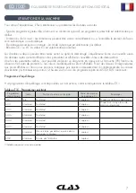
Страница 7: ...Start ou en abaissant le carter de protection les valeurs de déséquilibre seront affichées Poser des masses correspondantes aux poids affichés sur l écran aux positions indiquées puis lancer un deuxième test En règle générale les masses doivent être positionnées en position 12 heures sauf en cas de programme spécial ALS2 et ALS1 aluminium Programme d équilibrage Huit programmes d équilibrage sont ...

Страница 8: ... Position des masses d équilibrage Voir figure F1 détail 13 Remarque sélectionner le programme STANDARD désactive l affichage d équilibrage statique Le choix du programme influence également la saisie de données automatique des dimensions du pneumatique disponible uniquement sur certains modèles comme indiqué dans le tableau T3 1 La saisie de donnée automatique à 1 capteur se fait avec la pige dis...

Страница 9: ...s données est saisi manuellement Les équilibreuses automatiques ou semi automatiques dont les capteurs sont désactivés quelle qu en soit la raison se comportent comme des machines manuelles La saisie des données doit alors se faire manuellement et la position angulaire des masses d équilibrage se fera conformément à la procédure des machines manuelles Type de roues Il est possible de sélectionner ...

Страница 10: ...orsque la fonction roues moto est activée le déport est augmenté de 150 mm Figure F3 1 1 Mise en place de l adaptateur pour les roues de type moto Remarque sur les équilibreuses sans capteurs ou dont les capteurs se comportent comme des machines manuelles la saisie des données doit se faire manuellement Pour ce faire vous devez a placer l extrémité de la rallonge de la pige de déport sur la jante ...

Страница 11: ...valider en appuyant sur la touche P4 ou P5 Si vous n appuyez pas à temps l écran reviendra à l affichage précédent Dans ce cas vous pourrez revenir à la modification saisie de données en appuyant de nouveau sur la touche P1 5 Mesurer la largeur de la jante La largeur est généralment gravée à l intérieur de la jante Si ce n est pas le cas utiliser le compas La largeur peut être exprimée en pouces o...

Страница 12: ...9 Appuyer une fois sur la touche P3 pour voir le paramètre da1 diamètre du plan interne vous avez ensuite 1 5 seconde pour valider en appuyant sur la touche P4 ou P5 Si vous n appuyez pas à temps l écran reviendra à l affichage précédent Dans ce cas vous pourrez revenir à la modification saisie de données en appuyant de nouveau sur la touche P3 10 Appuyer deux fois sur la touche P3 pour voir le pa...

Страница 13: ...tre interne da1 Diamètre externe da2 ALS1 Da1 diamètre nominal de la jante Da2 diamètre nominal 2 0 inches ou 50 mm ALS2 Da1 diamètre nominal 1 0 inch ou 25 mm Da2 diamètre nominal 2 0 inches ou 50 mm Cette méthode ne requérant pas de prise de mesure manuelle elle est plus rapide Cependant les résultats peuvent être légèrement moins précis Figure F3 3 1 Exemple de prise de mesure du diamètre exter...

Страница 14: ...diamètre et les positionner sur le bord de la jante comme indiqué sur la figure F3 6 3 Attendre le bip long de saisie de données et repositionner ensuite les deux piges en position de repos 4 Saisir manuellement la largeur de la jante La largeur est généralement gravée à l intérieur de la jante Si ce n est pas le cas utiliser le compas Mesure automatique des paramètres de roue pour les programmes ...

Страница 15: ...ns de masses précises Avec le programme ALS1 l opérateur peut choisir librement la position d équilibrage interne alors qu avec le programme ALS2 il peut sélectionner à la fois les positions internes et fond de jante Seuls le déport et le diamètre sont pris en compte La mesure de largeur n est pas utilisée Les programmes ALS1 et ALS2 comportent trois étapes Saisie de données d équilibrage Rotation...

Страница 16: ...t une nouvelle saisie de données ce qui n a aucune conséquence 5 Repositionner immédiatement la pige de déport diamètre en position de repos Toute hésitation peut entraîner une mauvaise détection des plans d équilibrage auquel cas il suffit de répéter les opérations ci dessus 6 Positionner la pige de déport diamètre en fond de jante intérieur Voir figure F3 9 7 Maintenir la pige de déport diamètre...

Страница 17: ... que la pige se trouve sur le plan d équilibrage interne 5 Maintenir fermement la pige de déport diamètre à la bonne distance et positionner la masse adhésive sur la jante Le point de contact se situera entre 12 heures et 6 heures en fonction du diamètre de la jante Voir le tableau T3 3 6 Repositionner la pige de déport diamètre en position de repos Les indications à gauche et à droite de l écran ...

Страница 18: ...nné Dans ce cas les dimensions des plans d équilibrage di1 da1 et di2 da2 précédemment acquises seront utilisées pour afficher les valeurs de déséquilibre Si ces données ne sont pas disponibles les valeurs par défaut seront utilisées CALIBRATION Calibrer la machine vous garantit un fonctionnement optimal La calibration enregistre les paramètres spécifiques à chaque machine et améliore l équilibrag...

Страница 19: ...2 et P3 dimensions ou P4 et P5 valeurs Il n est pas possible de paramétrer les données avec le système de saisie automatique 9 Appuyer sur la touche P8 Start ou baisser le carter de protection la machine effectuera un lancement test 10 A la fin du test tourner manuellement la roue jusqu à ce que l écran affiche 50 g Positionner la masse étalon de 50g à 12 heures à l intérieur de la jante 11 Appuye...

Страница 20: ... en mode SERVICE 4 Appuyer sur la touche P3 Le message CAL CAR s affiche calibration pour roues voitures et tout terrain légers 5 Appuyer sur les touches P4 et P5 pour sélectionner la calibration moto MOTO La machine charge automatiquement les données géométriques de l adaptateur moto et paramètre le type de roues et le programme ALU1 6 Appuyer sur la touche P3 Le message CAL 0 s affiche 7 Appuyer...

Страница 21: ...ion angulaire des masses 12 La calibration MOTO est terminée l équilibreuse sort automatiquement du programme de calibration et se remet en mode NORMAL Elle est prête à être utilisée Pour toute calibration future les données MOTO et ALU1 seront utilisées de même que les dimensions de roues déterminées automatiquement pour ce type de calibration En cas d erreur pendant la phase de calibration des m...

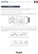
Страница 22: ...our retourner au programme précédent Appuyer sur les touches F P4 pour valider l option choisie Figure F5 1 Programme d optimisation Remarque il est possible de sortir du programme d optimisation à tout moment en appuyant sur les touches F P4 Icône 2 Si la valeur de masse statique est inférieure à 12 g un message d erreur s affiche automatiquement sur l écran pendant une seconde comme indiqué sur ...

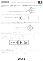
Страница 23: ...ue faite précédemment Baisser la carter de protection la machine effectue un lancement 7 A la fin du lancement le message indiqué sur la figure F5 3 s affiche Deux options sont alors disponibles a Positionner la valve à 12 heures et appuyer sur la touche P4 pour continuer le message indiqué sur la figure F5 7 s affiche b Appuyer sur les touches F P4 pour sortir du programme d optimisation et reven...

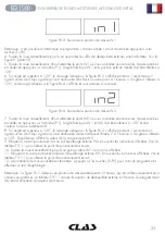
Страница 24: ...ogrammes et avec tout type de roue Il peut également être utilisé pour diviser la masse statique en deux particulièrement utile pour les roues moto Procédure à suivre pour effectuer le programme de masse cachée 1 Procéder à l équilibrage sans poser de masse extérieure 2 Appuyer sur les touches F P5 pour accéder au programme de masse cachée Si la roue est équilibrée du côté externe le message indiq...

Страница 25: ...t valider en appuyant sur la touche P1 L angle formé par W1 et W2 doit être inférieur à 120 et doit contenir la masse extérieure W 8 Si l angle est supérieur à 120 le message indiqué sur la figure F6 2 s affiche pendant 1 seconde et un signal sonore de 3 bips signale qu il est nécessaire de recommencer l étape 7 A l inverse si l angle est inférieur à 120 l équilibreuse affiche la valeur de la mass...

Страница 26: ...e pendant 1 seconde Figure F7 1 Activation de la mémoire d opérateur 2 La mémoire d opérateur 1 est enregistrée 2 Entrer les paramètres désirés dimensions de roue programme type de roue et unité de mesure Les paramètres d opérateur 1 sont enregistrés 3 Procéder à l équilibrage de la ou des roue s 4 Quand opérateur 2 a terminé opérateur 1 peut retrouver ses paramètres en appuyant sur les touches F ...

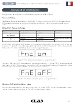
Страница 27: ... X1 au gramme près appuyer sur les touches F P1 Le message indiqué sur la figure F8 1 0a s affiche pendant 1 seconde et la LED correspondante s allume Les valeurs de déséquilibres sont maintenant affichées en précision X1 au gramme près Figure 8 1 0a Activation de la précision au gramme près Pour revenir à la précision X5 basse précision appuyer de nouveau sur les touches F P1 Le message indiqué s...

Страница 28: ...ue appuyer de nouveau sur les touches F P2 La LED correspondant à l affichage statique s éteint Remarque il est possible que l équilibreuse force le mode statique en fonction des paramètres définis Par exemple la machine se mettra automatiquement en mode d équilibrage statique si le programme MOTO est activé et que la largeur saisie est inférieure à 11 4 cm ...

Страница 29: ...29 EQ 1000 EQUILIBREUSE ROUES MOTORISEE AFFICHAGE DIGITAL ...

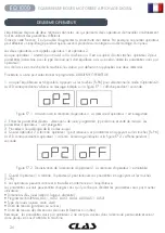
Страница 30: ...e F9 1 Figure 9 1 Mode SERVICE activé 3 Pour sortir du mode SERVICE il faut d abord sortir de tous les menus et de tous les programmes de test afin de revenir au message indiqué sur la figure F9 1 4 Appuyer sur les touches F P3 La machine repasse en mode NORMAL MENU P1 Calibration des capteurs de mesure Dans ce menu il est possible de tester et calibrer les capteurs de mesure de déport de diamètre...

Страница 31: ...sure actuellement sélectionnée est en inches appuyer sur la touche permettra de passer en millimètres et vice versa L unité choisie est affichée pendant une seconde puis est enregistrée et sera conservée en cas d arrêt de la machine MENU P6 Sélection du seuil d affichage des déséquilibres Cette touche permet d éditer le seuil d affichage des déséquilibres Cette procédure est réservée au SAV et n e...

Страница 32: ...figure F9 2 Ce message n apparait pas lorsque le matériau sélectionné est le fer zinc Figure F9 2 Choix du matériau plomb MENU F P3 Sortie du mode SERVICE Cette touche permet de sortir du mode SERVICE et de repasser en mode NORMAL MENU F P4 Affichage du nombre d équilibrage Cette touche permet d afficher le nombre total d équilibrage effectués sur les deux écrans La figure F9 3 montre un exemple d...

Страница 33: ...r le signal du capteur Afin d effectuer ce test il est nécessaire de monter une roue équilibrée jante tôle de 15 de diamètre et de 6 de largeur ou valeurs s en rapprochant le plus possible Une masse de 50 g doit être positionnée sur le flanc externe du pneumatique Appuyer sur la touche P8 Start déclenche une rotation continue Les signaux de capteurs relatifs aux trois procédures d atténuation atté...

Страница 34: ...hes puis arrêter ou redémarrer l équilibreuse de roues Si le problème persiste contacter le SAV 016 La pige déport n est pas correctement positionnée à la position 0 Repositionner la pige de déport en position de repos Si l erreur persiste contacter le SAV 017 La pige de largeur n est pas correctement positionnée à la position 0 Repositionner la pige de largeur en position de repos Si l erreur per...

Страница 35: ...ntrôler les codes d erreurs Bip court Bip long Mémorisation d une ou plusieurs valeurs dans la mémoire permanente Eprom de la carte mémoire Peut intervenir à la fin de la calibration Bip intermittent Réglages Signal d utilisation du programme de service pour faciliter le réglage des capteurs Un signal sonore se fait également entendre pendant 2 secondes au démarrage de l équilibreuse permettant ai...

Страница 36: ... démarre pas Le carter de protection est levé le message A Cr est affiché Abaisser le carter de protection L équilibreuse de roue propose des valeurs de déséquilibre instables 1 Quelque chose a fait bouger la machine pendant la rotation Renouveler l opération en s assurant que rien ne vienne perturber la saisie de données 2 La machine n est pas fermement posée au sol S assurer que le sol soit ferm...

Страница 37: ...propriée dans le respect des lois en vigueur LA PROCEDURE DE RECYCLAGE DECRITE CI DESSOUS S APPLIQUE EXCLUSIVEMENT AUX MACHINES DONT LA PLAQUE EST ORNEE D UNE POUBELLE BARREE Le symbole représentant une poubelle barrée indique que le produit en fin de vie doit être recyclé de manière appropriée Le produit contient peut être des substances dangereuses pour l environnement ou pour la santé Les infor...

Страница 38: ...dre Oui CO2 Oui Oui peut être utilisé si aucun autre appareil n est à disposition ou pour les incendies mineurs ATTENTION Les informations contenues dans le tableau précédent sont données à titre d information Les conditions exactes d utilisation de chaque type d extincteur doivent être obtenues auprès du fabriquant ...

Страница 39: ... up and diagnostics 43 Use of the machine 44 Calibration 55 Optimisation 59 Hidden weights programme 61 Second operator 63 Utility programmes 64 Service mode 67 Signals 71 Troubleshootings 73 Maintenance 74 Machine demolition 74 Environmental informations 74 Fire extinguishing materials 75 ...

Страница 40: ...rogramme selected 2 Indicator light red for the selected unit of measure inches on mm off 3 8 Display for viewing internal external imbalance 4 9 Indicator light for the internal external angular imbalance position 5 Active standby status indicator light 6 Enabling on disabling off indicator light of the automatic acquisition system of the wheel size 7 Indicator light for the selected Programme Ty...

Страница 41: ...ou want the secondary function simultaneously and then release both the keys Table T1a Settings programmes and Menu available in the SERVICE mode press F P3 to enter the mode Key Setting programme or menu Key Setting programme or menu P1 MENU programme for sensor calibration F P1 Not used P2 Not used F P2 Select weight material in Fe Zn or P P3 Machine calibration F P3 Exit SERVICE mode return to ...

Страница 42: ...tures three operating modes NORMAL mode This mode is enabled when the machine is switched on and allows the use of the machine to run wheel balancing SERVICE mode In this mode there are a number of utility programmes available to enter settings e g unit of measure in grams or ounces or controls for machine operation such as calibration STAND BY mode After 5 minutes of inactivity the machine automa...

Страница 43: ...43 EQ 1000 MOTORIZED WHEEL BALANCER WITH DIGITAL DISPLAY START UP AND DIAGNOSTICS Once the machine is started it runs the actions shown in diagram below Diagram Programme flow at machine start up EQ2000 ...

Страница 44: ...ve been entered you can run a launch by pressing P8 Start or by lowering the wheel guard At the end of the launch the machine displays the wheel imbalance values Apply the weights displayed by the machine at the indicated positions and then run a second test launch Normally the weights should be applied at the 12 o clock position with the exception of special programmes for ALS2 and ALS1 aluminium...

Страница 45: ...e the following LEDs are lit on the control panel Programme type LED See figure F1 detail 7 Weight Imbalance Position LED See figure F1 detail 13 Note The selection of the STD Programme Type removes the selection of the Static imbalance display The selected Programme Type also influences the automatic acquisition of wheel dimensions feature available only on some models of the machine as shown in ...

Страница 46: ...stems are defined as follows Manual when the data of the rim must be all entered manually Automatic or Semi Automatic machines with the sensors disabled due to failure or for any other reason become to all intents Manual machines Entering the dimensions of the rims must be carried out manually and the angular position of the balancing weights will follow the procedures of the Manual machines Wheel...

Страница 47: ...heel type is enabled the current distance value is automatically increased by 150 mm in order to take account of the length of the extension for the Distance sensor Figure F3 1 1 Application of the extension of Distance Diameter sensor for measuring MOTO wheel type Note on machines without automatic sensor or on machines where the automatic distance sensor is disabled the distance data must be ent...

Страница 48: ... graduated scale as shown in figure F3 3 The distance value is always expressed in millimetres 4 Press P1 to modify the distance and then press P4 or P5 within 1 5 seconds to enter the read value If you do not press buttons P4 or P5 within this time limit the machine will return to the previous display In this case you can press P1 again to enter or edit data 5 Measure the width of the wheel with ...

Страница 49: ... P4 or P5 within 1 5 seconds to enter the value resulting from one of the two me thods described in the note below If either one of these two buttons is not pressed in this time frame the machine will return to the previous screen In this case you can press P3 again to enter or edit data 10 Press the button P3 twice in rapid sequence to view da2 diameter of the external plane and buttons P4 or P5 ...

Страница 50: ...ALS2 da1 nominal diameter 1 0 inch or 25 mm da2 nominal diameter 2 0 inches or 50 mm Since manual measuring is not required this method is faster but the results may be slightly less accurate Figure F3 3 1 1 Example of manual measuring of the external diameter da2 of the wheel in the ALS1 ALS2 Programme Type Figure F3 4 Manual Acquisition of wheel distance in the ALS1 Programme Type Figure F3 4 Ma...

Страница 51: ...in Figure F3 6 3 Wait to hear the long acquisition beep and then set the Distance Diameter sensor back to the rest position 4 Introduce rim width manually The width of the rim is normally printed on the rim itself Alternatively use the appropriate width measuring gauge Automatic acquisition of the wheel dimensions for the ALS1 and ALS2 Programme Types To automatically enter the dimensions of the w...

Страница 52: ... lies in the fact that in the ALS1 Programme Type the user can freely choose only the external balancing plane the internal plane is in a predetermined position whilst in the ALS2 Programme Type the user can freely choose both balancing planes The ALS1or ALS2 Programme Types use only the Distance Diameter sensor to acquire the balancing planes chosen by the user The Width sensor is not used Use of...

Страница 53: ...he rest position for a longer time further acquisition probing of that plane will be run without entailing consequences 5 Set the Distance Diameter sensor in the rest position immediately If you hesitate with this operation the machine may detect an incorrect plane in this case restore the sensor in rest position and repeat acquisition procedure 6 Extract the Distance Diameter sensor and place it ...

Страница 54: ...ernal balancing plane Figure F3 15 Balancing planes search the left display indicates that the sensor is exactly on the internal balancing plane 5 Keep the Distance Diameter sensor blocked at this distance then rotate it until the adhesive weight sticks on the rim The sensor s contact point on the rim will assume an intermediate position between 12 o clock and 6 o clock depending on the diameter o...

Страница 55: ...sing the balancing planes i e the two di1 da1and di2 da2 dimension pairs previously acquired or lacking these the default balancing planes CALIBRATION To operate the machine properly it must be calibrated Calibration allows storing the mechanical and electrical parameters specific to each machine so as to provide the best balancing results When to carry out machine calibration Table T4 lists the c...

Страница 56: ...Note the calibration for motorbike wheels is described separately in chapter 4 3 Machine calibration for MOTO Wheel Type 6 Press P3 The writing CAL0 will be displayed 7 Press P8 Start or lower the wheel guard The machine will run a launch and will show the writing CAL1 on the display once completed 8 Mount the wheel on the shaft and enter its dimensions by pressing the keys P1 P2 P3 to select the ...

Страница 57: ...hine will not run the launch and will display the error code ERR 03 To calibrate motorbike wheels proceed as follows 1 Switch the machine on 2 Apply the flange on the shaft for motorbike wheels as shown in Figure F4 1 Figure F4 1 Application of the motorbike flange onto the shaft Align the writing Cal on the flange and on the flange for motorbikes 3 Press F P3 The writing SER SER will be displayed...

Страница 58: ...or message triple beep 12 Once the calibration launch for the MOTO Wheel Type is completed the machine returns directly to the NORMAL mode ready to perform the balancing When the machine completes calibrating the MOTO Wheel Type and the ALU1 Programme Type will remain set Even the dimensions of the wheel will remain those set automatically by the machine for this type of calibration If there are s...

Страница 59: ...option oPt 1 to continue or the option oPt rEt to return to the operating programme Press F P4 to confirm the chosen option Figure F5 1 Access to the Optimisation programme Note you can exit the calibration procedure at any time by repeatedly pressing F P4 2 If the wheel s static imbalance is less than 12 grams the machine will display the message shown in Figure F5 2 for a second and then will au...

Страница 60: ...age seen in figure F5 3 will be displayed Two options are available a Bring the valve to the 12 o clock position and press P4 to continue In this case the message seen in figure F5 7 will be displayed b Press F P4 to exit the optimisation programme and to directly return to the operating programme Fig F5 7 Final valve alignment with the mark on the tyre message 8 Rotate the wheel until all positio...

Страница 61: ...Type and with any Wheel Type It can also be used to divide the static weight into two separate weights especially useful with wheels for motorbikes To use this programme proceed as follows 1 Perform the balancing of the wheel without applying the external weight 2 Press F P5 to run the Hidden Weights programme If the wheel is balanced on the external side the machine will display the message shown...

Страница 62: ...the weights W1 and W2 must not be less than 120 and must include the external weight W 8 If the chosen angle is greater than 120 the machine will display Fig F6 2 for one second and will emit a triple beep meaning to repeat the procedure in step 7 again If the angle instead is less than 120 the machine will immediately display the value of the external weight W2 9 Block the wheel and apply the ext...

Страница 63: ...ory of operator 1 is stored 2 Perform all desired settings for wheel dimensions Programme Type Wheel Type and unit of measure The settings of operator 1 are stored in memory 3 Perform balancing of the wheel or wheels 4 When operator 2 has finished his task on the balancing machine operator 1 presses F P6 and thus restores all settings used by the latter The LED located next to the button will turn...

Страница 64: ... Ounces 0 25 ounces To view the imbalance in X1 resolution high resolution press F P1 The machine will display the message visible in Figure F8 1 0a for one second and the LED next to the button will turn on Imbalance values are now displayed in X1 resolution high resolution Fig F8 0a Enabling of the imbalance display in high resolution To return to viewing in X5 resolution low resolution press F ...

Страница 65: ...lance To return to the dynamic imbalance display press F P2 again The LED next to the button will turn off Note in some cases static imbalance is forcibly set by the machine according to the current settings For example if the MOTO Wheel Type programme is enabled and the width set is less than 4 5 inches the machine will auto matically set the static imbalance display ...

Страница 66: ...de you must first exit any Menus and test programs and return to the messages display shown in Figure F9 1 4 Press F P3 the machine will return to the NORMAL mode P1 MENU Sensor calibration programmes This menu allows running the test and or calibration of the sensors for measuring Distance Diameter and Width The Menu has the following options DiS Distance sensor test Ret Returns to the Service mo...

Страница 67: ...f measure of the wheel dimensions if the unit of measure selected is in inches select mm and vice versa This selection is maintained even when the machine is shut down The unit of measurement selected will be displayed for one second P6 Select the imbalances view threshold This button allows editing the imbalances view threshold This procedure is intended for technical support personnel and is not...

Страница 68: ...lected as material Ce message n apparait pas lorsque le matériau sélectionné est le fer zinc Figure F9 2 Selection of the Lead balancing weights F P3 Exit the SERVICE mode This button allows the machine to exit the SERVICE mode and return to the NORMAL mode F P4 Read launch number counter By pressing this button the total number of balancing launches run by the machine will be displayed The number...

Страница 69: ... F P9 SIG Pick up signals test This programme allows checking the pick up signal To run the test you will need to mount a balanced wheel with steel rim 15 in diameter and 6 in width or more similar as possible on the machine A 50 g weight must be applied the external side of the wheel By pressing P8 Start the machine will run continuous spinning and the pick up signals respect to the three attenua...

Страница 70: ...ort 016 Distance sensor not in rest position when the machine is switched on Set the sensor to its rest position the error should disappear If the error persists contact technical support 017 Width sensor not in rest position when the machine is switched on Set the sensor to its rest position the error should disappear If the error persists contact technical support 018 Reserved 019 Communication ...

Страница 71: ...ed function is not available or that an error condition has occurred Short beep long beep Storing one or more values in the permanent memory eeprom of the circuit board One or more values have been stored in the permanent memory of the circuit board for example at completion of calibration phases Intermittent beep Adjustment Signal used in some service programmes to simplify the adjustment of sens...

Страница 72: ... to spin the machine does not start The wheel guard is raised the A Cr message is displayed Lower the guard The wheel balancer provides unsteady unbalance values The machine was jolted during the spin Repeat the wheel spin while making sure that nothing affects machine operation while acquisition is in progress The machine does not firmly rest on the floor Make sure that the floor support is firm ...

Страница 73: ... ethyl alcohol to clean the display panel Perform the calibration procedure at least once every six months If the machine is to be scrapped remove all electrical electronic plastic and metal parts and dispose of them separately in accordance with current provisions as prescribed by law The following disposal procedure shall be exclusively applied to the machines having the crossed out bin symbol o...

Страница 74: ...d of the life of your product When purchasing this product your distributor will also inform you of the possibility to return another end of life piece of equipment free of charge as long as it is of equivalent type and had the same functions as the purchased product Any disposal of the product performed in a different way from that described above will be liable to the penalties provided for by t...

Страница 75: ...NOTES ...
Страница 76: ...s ou de pièces contactez le revendeur En cas de problème veuillez contacter le technicien de votre distributeur agréé If you need components or parts please contact the reseller In case of problems please contact your authorized technician CLAS Equipements ZA de la CROUZA 73800 CHIGNIN FRANCE Tél 33 0 4 79 72 62 22 Fax 33 0 4 79 72 52 86 EQ 1000 ...

Отзывы:

Похожие инструкции для EQ 1000