Digital Multimeter • Article number 36-2287 • Model BX3604W
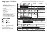
1. Safety regulations
•
The measuring instrument has been developed and tested in accordance
with the IEC 61010-1 installation category (over voltage category) ) II 600 V
and on contamination category II.
•
The measuring instrument has been tested in accordance with the following
EMC directive:
o 89/336/EEC (EMC November 1992. electromagnetic compatibility)
o The low voltage directive 73/23/EEC. EN61010-1 (04. 93)
•
The measuring instrument has been developed for indoor use with working
temperatures of b5C° and +40C° up to a height of 2000 meters.
•
By following all safety rules and operation instructions you will guarantee that
the measuring instrument is used safely.
•
Do not use the instrument if testing cables appear damaged; or if you
suspect that the instrument is not functioning as it should.
•
Make sure that your fingers are behind the testing cables’ finger guard when
using the testing cables.
•
Check that the power supply is switched off before performing any
maintenance of the circuit board! Even small currents can be dangerous.
•
Do not measure higher voltages than 600 VDC or 600 VAC rms between an
output and earth.
•
To avoid electric shock you should be CAREFUL when working with higher
a voltage than 60 VDC or 25 VAC rms. Higher voltage increases the risk of
powerful shocks.
•
Never use the instrument if the battery cover or battery slot is open.
•
To avoid electric shock or damage to the measuring instrument, the
measuring limit for the instrument should not be exceeded. The guarantee
does not apply if the instrument has been used incorrectly.
•
The instrument is protected by a fuse but it does not protect the instrument
from all types of incorrect use .
2. International symbols
!
Important information see manual
AC
Buzzer tone
DC
Earth
LED
Double insulation
3. Specification
3.1 General Specification
Display:
3 ½ digit LCD display with a maximum value of 1999
Polarity:
automatic indication of (-) negative polarity
Resetting:
automatic
Indication when measurement value exceeds Range of measurement:
only “1” is displayed
Power supply:
9 V battery. 6F22
Overloading protection:
Fuse 5x20mm F (fast). 200 mA/250 V
Size:
94 x 205 x 62 mm
Weight:
Approximately 620 g (with battery and box)
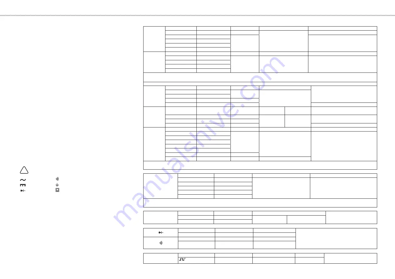
3.2 Electrical Specifications
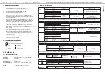
DC V
Range
Resolution
Accuracy
Input impedance
Overload protection
200 mV
0.1 mV
+/- (0.8 % +1)
10 MΩ
250 V DC /AC rms
2 V
0.001 V
+/- (0.8 % +1)
600 V/DC/AC rms value (rms)
20 V
0.01 V
200 V
0.1 V
600 V
1 V
AC V
Range
Resolution
Accuracy
Frequency response
Input impedance 10 MΩ
2 V
0.001 V
+/- (0.8 % +3)
+/- (1.2 % +3)
40 – 400 Hz
Overload protection
600 V DC/AC rms value (rms)
20 V
0.01 V
200 V
0.1 V
600 V
1 V
In measurement Range “2VAC” the display shows a measurement value whether the testing cables short circuit or not. This measurement value should NOT be subtracted
from the measurement value shown during voltage measurement.
DC A
Range
Resolution
Accuracy
Voltage drop
Fast 200 mA/250 V Fused
2 mA
0.001 mA
+/- (0.8 % +3)
200 mV
20 mA
0.01 mA
200 mA
0.1 mA
+/- (1.0 % +3)
20 A
0.01 A
+/- (2.0 % +5)
15 seconds maximum without fuse
Range
Resolution
Accuracy
Frequency
Range
Voltage drop
Overload protection
20 mA
0.01 mA
+/- (1.2 % +3)
40 – 400 Hz
200 mV
Fast fuse: 200 mA/250 V
200 mA
0.1 mA
+/- (1.5 % +3)
20 A
0.01 A
+/- (3.0 % +5)
15 seconds maximum without fuse
Resistance
Range
Resolution
Accuracy
Voltage unstressed input
200 Ω
0.1 Ω
+/- (0.8 % +2)
< 700 mV
Overload protection
250 VDC/AC (rms) < 30 seconds
2 kΩ
0.001 kΩ
20 kΩ
0.01 kΩ
200 kΩ
0.1 kΩ
2 MΩ
0.001 MΩ
20 MΩ
0.01 MΩ
+/- (1.0 % +2)
200 MΩ
0.1 MΩ
+/- (5.0 % +10)
< 3 V
In measurement Range“200 MΩ” the display shows a measurement value whether the testing cables short circuit or not. This measurement value SHOULD be subtracted
from the measurement value shown during resistance measurement.
Capacitance
Range
Resolution
Accuracy
Test frequency
2 nF
0.001 nF
+/- (2.5% + 5)
400 Hz
20 nF
0.01 nF
200 nF
0.1 nF
2 μF
0.001 μF
20 μF
0.01 μF
In measurement Range ”2nF” the display shows a value despite the fact that no component is connected to the Cx socket. This measurement value should NOT be
subtracted from the measurement value shown during capacity measurement.
Frequency
Range
Resolution
Accuracy
Overload protection 250 VDC/AC
(rms) < 30 seconds
2 kHz
0.001 kHz
+/- (1.5% + 5)
V min >150 mV
V maximum< 10 V
20 kHz
0.01 kHz
Test voltage
Measurement current
Voltage unstressed input
Overload protection 250 VDC/AC (rms) < 30 seconds
Ca. 2.8 V
Ca: 1 mA
Ca: 2.8 V
Range
Measurement current
Open circuit voltage
Buzzer is heard when
resistance is ≤ 60 Ω
Ca 1 mA
2.8 V
Wave generator
Range
Output voltage
Frequency
Waveform
Overload protection 250 VDC/AC
(rms) < 30 seconds
OUT
2.3V p-p
50Hz
Square wave
Ver. 20080
2
Please read the entire instruction manual before using and save it for future use. We apologise for any text or photo errors and any changes
of technical data. If you have any questions concerning technical problems please contact our Customer Service Department.


