


27
Parts & Service: 020 8988 7400 / E-mail: [email protected] or [email protected]
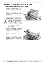
ADJUSTING THE SHEAR TABLE
1. Loosen the cap screws on either
end of the shear table that secure
it to the machine (see Figure 45).
2. Evenly rotate the table
adjustment screws to adjust the
position of the shearing table until
the blade gap is even, then re-
tighten the cap screws to secure
the table in place.
NOTE:
Rotating the table
adjustment screws clockwise moves the table toward the upper
shear blade.
3. Perform the previous shear test.
4. If necessary, repeat Steps 1-3 until you are satisfied with the shear test cut.
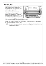
ADJUSTING THE BLADE BOW
The adjustment bolt of the blade
bow is used to remove any slight bow
in the cast iron cross beam that the
brake finger receiver and upper
shear blade are attached to (see
Figure 46).
TO ADJUST THE BLADE GAP WITH THE BLADE BOW:
1. Hold the adjustment bolt still, then turn the jam nut to adjust the center of
the cross beam in or out (see Figure 46).
• If the shear test cut was clean on the ends of the shear table but not
in the middle, turn the jam nut counterclockwise to force the
adjustment bolt against the cross beam, moving it in toward the
front.
• If the shear test cut was clean in the middle but not on the ends,
rotate the jam nut clockwise to allow the cross beam to move back.
2. Perform the previous shear test.
3. If necessary, repeat Steps 1-2 until you are satisfied with the shear test cut.
Fig. 45
Fig. 46


