2
Features
- Combination 25/70/100V transformer (SX15-T,
SX30-T, SX15-TM)
- Weather resistant construction
- High impact plastic housing in beige, gray or
white housing
- Marine version - no fade, white sealed housing
- Fully adjustable 360 degrees horizontal and 90
degrees vertical
- Rotary switch for tap selection
- Stainless steel hardware
- Beam mount clamp or electrical backbox
Environment
- Temperature:
0 to +50 Degrees C
- Humidity:
0 to 85%
Horn Taps for the SX15-T, SX15-TM
15 Watts, 25/70/100 Volts
Switch Setting
100V
70V
25V
Set
Ohms
1.9
-
-
1
5333
3.8
1.9
-
2
2667
7.5
3.8
-
3
1333
15
7.5
-
4
667
-
15
1.9
5
333
-
-
3.8
6
167
-
-
7.5
7
83
-
-
15
8
42
Horn Taps for the SX30-T
30 Watts, 25/70/100 Volts
Switch Setting
100V
70V
25V
Set
Ohms
1.9
-
-
1
5333
3.8
1.9
-
2
2667
7.5
3.8
-
3
1333
15
7.5
-
4
667
30
15
1.9
5
333
-
30
3.8
6
167
-
-
7.5
7
83
-
-
15
8
42
-
-
30
9
21
Specifications
Frequency Response and Maximum Power
Handling Capability
SX15-T
300 - 10K
15 Watts
SX15-TM
300 - 10K
15 Watts
SX15-8
300 - 10K
15 Watts
SX30-T
300 - 10K
30 Watts
SX30-8
300 - 10K
30 Watts
SPL @ 4 feet at 1 Watt at 1K
SX15-T
105dB
SX15-TM
105dB
SX15-8
105dB
SX30-T
107dB
SX30-8
107dB
Line Voltage
•
25/70/100V (SX15-T, SX15-TM, SX30-T)
•
8 Ohms (SX15-8, SX30-8)
INSTALLATION
Cabling
Standard two conductor shielded cable (18-20AWG)
can be used for connections.
Connections
Connect station or other suitable wire to leads as
follows:
Page
Out.......................................Tip
Control
Common........................... Ring
Unit
Attaching Speaker to Base
NOTE: For ease of installation, the base can be
attached to the speaker before or after the base is
mounted.
•
Loosen position adjustment knob.
•
Insert the ball of the base into the socket of the
speaker.
•
Tighten the position adjustment knob.
Mounting/Positioning
Mount the horn to a suitable surface using the
hardware provided. These units can be mounted to a
wall, a beam or an electrical box.
•
Mount the base to a wall using the two holes
provided. Knockout holes are provided for
punch out should additional holes be required.
•
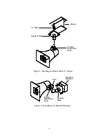
A "C" clamp is provided with the horns to allow
mounting to a beam. Place the bolt through the
hole in the bottom of the base to secure the "C"
clamp to the beam (See Figure 1).


