


SINGLE BOARD COMPUTER
User`s Manual
Version 1.0
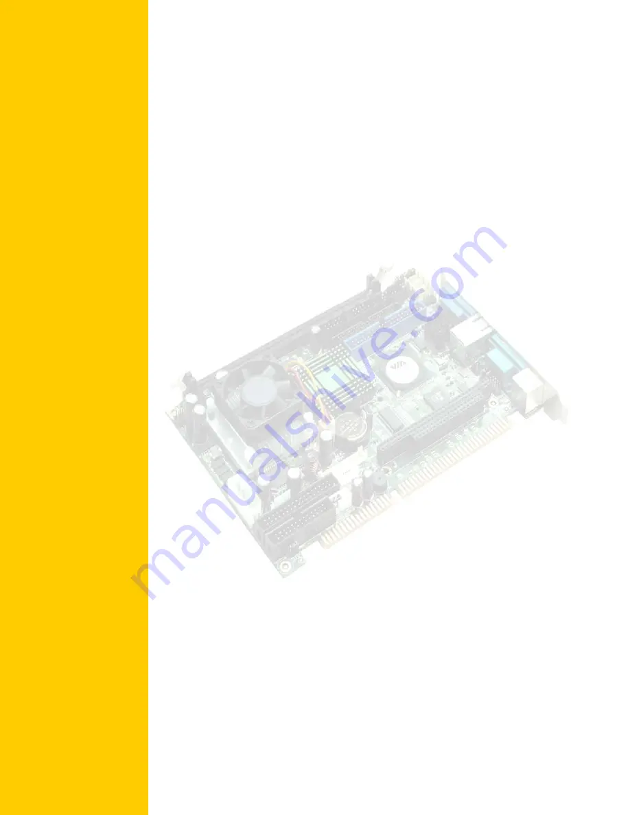
CJ ISA-E5
CJB Computer Job S.r.l.
www.cjb.it ~ [email protected]
Содержание CJ ISA-E5
Страница 10: ...2 ISA E5 User s Manual Chapter 1 Features Specifications Features 3 Specifications 4...
Страница 15: ...ISA E5 User s Manual 7 Dimensions 185mm W x 127mm L 4 screw holes on four corners...
Страница 16: ...8 ISA E5 User s Manual This page is intentionally left blank...
Страница 17: ...ISA E5 User s Manual 9 Chapter 2 Jumper setting Connectors Jumpers on the ISA E5 10 Connectors on the ISA E5 15...
Страница 19: ...ISA E5 User s Manual 11 Jumper Locations on the ISA E5...
Страница 24: ...16 ISA E5 User s Manual Connector Locations on the ISA E5...
Страница 87: ...ISA E5 User s Manual 79 CHAPTER 4 Appendix I O Port Address Map 80 Interrupt Request Lines IRQ 81 POST Beep 82...