


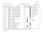


4-2. Troubleshooting
4-7
CLP-621 & CLP-631
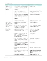
4-2-3. Problems in Printing
Symptoms
Checks
Remedies
No print
1. Is the head block securely closed?
2. Is the thermal head over heated?
3. Is the PF motor over heated?
4. Is the take-up side ribbon motor
(Ribbon Motor F SA) over heated?
5. Is the interface cable firmly connected
between the printer and the host?
6. Is the Centro cable firmly connected
between the Cenntro PCB Unit
(CN101) and the Main PCB Unit
(CN18)?
7. Is the print head cable firmly connected
between the Head SA and the Main
PCB Unit (CN4)?
8. Does the transparent/reflective sensor
detect presence of media?
9. Is +24V supplied to the test point T18?
10. Head SA is broken.
11. Failure in the head driver circuit.
12. Failure in the control circuit.
1. Close the head block correctly.
2. Wait until the thermal head gets
cool. Printing resumes
automatically.
3. Wait until the PF motor gets cool.
Printing resumes automatically.
4. Wait until the Ribbon Motor F SA
gets cool. Printing resumes
automatically.
5. Connect it firmly.
6. Connect it firmly.
7. Connect it firmly.
8. To check, see 4-2-5 "Sensor
Problems".
9. Replace the Power Supply Unit.
10. Replace the Head SA.
11. Replace the Head SA.
12. Replace the Main PCB Unit.
Poor printing
1. Thickness adjustment is improper.
2. Is +24V supplied to the test point T18
low?
1. Adjust the media thickness
adjustment dial to suit to the media
thickness being used.
2. Replace the Power Supply Unit.
Uneven print density
1. Head balance is improper.
Uneven print density may appear either
on the right side or the left side.
1. Adjust the media width adjustment
dial to suit to the media width
being used.
Содержание CLP-621
Страница 1: ...Technical Manual CLP 621 CLP 631 Thermal Transfer Barcode Label Printer JM74961 00F 1 00E 0701...
Страница 2: ...CLP 621 CLP 631 ii Copyright 2007 by CITIZEN SYSTEMS JAPAN CO LTD...
Страница 4: ...CHAPTER 1 SPECIFICATIONS CLP 621 CLP 631...
Страница 13: ...CHAPTER 2 OPERATING PRINCIPLES CLP 621 CLP 631...
Страница 68: ...2 5 Power Supply CLP 621 CLP 631 2 56 N1 N2 N3 N4 BLOCK A BLOCK E BLOCK B BLOCK C BLOCK D 120V type...
Страница 69: ...2 5 Power Supply 2 57 CLP 621 CLP 631 N1 N2 N3 N4 Block A Block B Block C Block E Block D 220 240V type...
Страница 73: ...CHAPTER 3 DISASSEMBLY AND MAINTENANCE CLP 621 CLP 631...
Страница 126: ...CLP 621 CLP 631 CHAPTER 4 TROUBLESHOOTING...
Страница 138: ...CLP 621 CLP 631 CHAPTER 5 PARTS LISTS...
Страница 143: ...Chapter 5 Parts Lists CLP 621 CLP 631 5 6 DRAWING NO 1 General Assembly Rev 0 1 7 8 2 3 4 2 10 11 12 9 5 2 13 14 10...
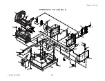
Страница 163: ...Chapter 5 Parts Lists CLP 621 CLP 631 5 26 DRAWING NO 6 Sensor U Unit Rev 0 4 16 3 2 1 9 10 11 5 8 6 12 7 13 14 15...
Страница 166: ...Chapter 5 Parts Lists CLP 621 CLP 631 5 29 DRAWING NO 7 Control Panel Unit Rev 0 4 3 2 1 5...
Страница 174: ...Chapter 5 Parts Lists CLP 621 CLP 631 5 37 DRAWING NO 9 Ribbon Unit Fan SA2 Rev 0 1 2 4 3 5 6 3...
Страница 177: ...Chapter 5 Parts Lists CLP 621 CLP 631 5 40 DRAWING NO 10 Accessories Rev 0 3 2 4 1...
Страница 179: ...CHAPTER 6 CIRCUIT DIAGRAMS CLP 621 CLP 631...
Страница 208: ...APPENDICES CLP 621 CLP 631...
Страница 211: ...B Mounting Diagrams B Mounting Diagrams B Mounting Diagrams CLP 621 CLP 631 AP 4 AP 4 B 1 Main PCB Main PCB Parts side...
Страница 212: ...B Mounting Diagrams AP 5 CLP 621 CLP 631 Main PCB Solder side...
Страница 213: ...B Mounting Diagrams CLP 621 CLP 631 AP 6 AP 6 B 2 Power Supply PCB 120V 220V B 2 Power Supply PCB 120V 220V...
Страница 214: ...B Mounting Diagrams AP 7 CLP 621 CLP 631 B 3 Ribbon Main PCB Parts side Solder side...
Страница 217: ......


