


4-2. Troubleshooting
4-5
CLP-621 & CLP-631
4-2. Troubleshooting
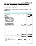
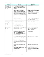
The following tables show possible remedies for various symptoms that might occur. Symptoms
are given in the left column, and the corresponding remedies in the right column.
Notes:
1. When parts are replaced, refer to Chapter 3 "Disassembly and Maintenance".
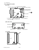
2. Connectors (CN . . .) given in the column of checks and remedies are connected with
the Main PCB Unit. For the location of each connector, refer to 4-2-7 "Connector
Location".
4-2-1. Problems in Powering Up the Printer
Symptoms
Checks
Remedies
No power to the
printer
1. Check voltage on the input power line.
Acceptable supply voltage:
120V (-10%+6%) for 120V version
220V-240V (-10%+6%) for 220V version
2. Is the fuse F1 on the Power Supply Unit
blown?
3. Is the Power Cable SA firmly connected
between the Power Supply Unit and the
Main PCB Unit (CN10)?
4. Is the Ope-pane Cable connected
between the Main PCB Unit (CN12)
and the Ope-Pane PCB SA firmly?
If it is not connect or is inserted upside
down, no LED lights even if you turned
ON the power.
5. Failure in the power supply circuit.
1. Supply correct voltage.
2. Replace with new fuse. If new fuse
is also blown when power is turned
on with the connector CN10
disconnected from the Main PCB
Unit, the Power Supply Unit is
faulty and must be replaced.
Notes:
- Do not replace the fuse with the
power switch turned on.
- The fuse is provided to prevent
fire, and damage to the Power
Supply Unit. When replacing it,
use the same rating and type.
3. Connect it firmly.
4. Connect it firmly.
5. Replace the Power Supply Unit.
Содержание CLP-621
Страница 1: ...Technical Manual CLP 621 CLP 631 Thermal Transfer Barcode Label Printer JM74961 00F 1 00E 0701...
Страница 2: ...CLP 621 CLP 631 ii Copyright 2007 by CITIZEN SYSTEMS JAPAN CO LTD...
Страница 4: ...CHAPTER 1 SPECIFICATIONS CLP 621 CLP 631...
Страница 13: ...CHAPTER 2 OPERATING PRINCIPLES CLP 621 CLP 631...
Страница 68: ...2 5 Power Supply CLP 621 CLP 631 2 56 N1 N2 N3 N4 BLOCK A BLOCK E BLOCK B BLOCK C BLOCK D 120V type...
Страница 69: ...2 5 Power Supply 2 57 CLP 621 CLP 631 N1 N2 N3 N4 Block A Block B Block C Block E Block D 220 240V type...
Страница 73: ...CHAPTER 3 DISASSEMBLY AND MAINTENANCE CLP 621 CLP 631...
Страница 126: ...CLP 621 CLP 631 CHAPTER 4 TROUBLESHOOTING...
Страница 138: ...CLP 621 CLP 631 CHAPTER 5 PARTS LISTS...
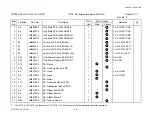
Страница 143: ...Chapter 5 Parts Lists CLP 621 CLP 631 5 6 DRAWING NO 1 General Assembly Rev 0 1 7 8 2 3 4 2 10 11 12 9 5 2 13 14 10...
Страница 163: ...Chapter 5 Parts Lists CLP 621 CLP 631 5 26 DRAWING NO 6 Sensor U Unit Rev 0 4 16 3 2 1 9 10 11 5 8 6 12 7 13 14 15...
Страница 166: ...Chapter 5 Parts Lists CLP 621 CLP 631 5 29 DRAWING NO 7 Control Panel Unit Rev 0 4 3 2 1 5...
Страница 174: ...Chapter 5 Parts Lists CLP 621 CLP 631 5 37 DRAWING NO 9 Ribbon Unit Fan SA2 Rev 0 1 2 4 3 5 6 3...
Страница 177: ...Chapter 5 Parts Lists CLP 621 CLP 631 5 40 DRAWING NO 10 Accessories Rev 0 3 2 4 1...
Страница 179: ...CHAPTER 6 CIRCUIT DIAGRAMS CLP 621 CLP 631...
Страница 208: ...APPENDICES CLP 621 CLP 631...
Страница 211: ...B Mounting Diagrams B Mounting Diagrams B Mounting Diagrams CLP 621 CLP 631 AP 4 AP 4 B 1 Main PCB Main PCB Parts side...
Страница 212: ...B Mounting Diagrams AP 5 CLP 621 CLP 631 Main PCB Solder side...
Страница 213: ...B Mounting Diagrams CLP 621 CLP 631 AP 6 AP 6 B 2 Power Supply PCB 120V 220V B 2 Power Supply PCB 120V 220V...
Страница 214: ...B Mounting Diagrams AP 7 CLP 621 CLP 631 B 3 Ribbon Main PCB Parts side Solder side...
Страница 217: ......


