


3-6. Adjustments
CLP-621 & CLP-631
3-50
Removing Ribbon Wrinkles
T
he following explains the general procedure for removing ribbon wrinkles.
Adjusting points:
• Ribbon tension
• Ribbon Left-Right Balance Adjustment Knob (Front) - Ribbon slant
• Ribbon Left-Right Balance Adjustment Knob (Rear) - Ribbon slant
• Ribbon Guide Shaft (a part of the Head SA) - Ribbon slant
How to check ribbon wrinkles:
• Visual check
Adjustment procedure:
First, adjust the ribbon tension and then the ribbon paths (front/rear) to remove ribbon wrinkles.
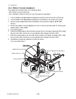
(1) Ribbon Tension Adjustment
1. Adjust the ribbon tension on the front and rear sides to obtain the specified value. Refer to
3-6-3 “Ribbon Tension Adjustment”.
2. Proceed to the next item, (2).
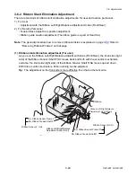
(2) Ribbon slant elimination adjustment
Ribbon is fed from the supply side and taken up on the take-up side via the Ribbon Tension
Shaft R SA of the Ribbon Sensor R Unit and the Ribbon Tension Shaft F SA of the Ribbon
Sensor F Unit. (See the figure on the next page.)
1. Adjust the Ribbon Left-Right Balance Adjustment Knob (Front) and then the Ribbon
Left-Right Balance Adjustment Knob (Rear) to remove ribbon wrinkle.
Refer to 3-6-2-(1) “Ribbon slant elimination adjustment (For user)”.
2. If satisfactory results are not obtained, the following adjustments will be required.
• 3-6-2-(2-1) “Tension base adjust cam position adjustment (For service personnel)”.
• 3-6-2-(2-2) “Ribbon guide position adjustment in the Head SA (For service personnel)”.
(2-1) Visual check and adjustment
Checking the ribbon surface visually is a good way to see whether the ribbon wrinkles or
not. You can find wrinkles by the reflected light on the ribbon surface. Check both take-up
side and supply sides of ribbon. (See the figure on the next page to find the places where
wrinkles may appear.)
Note:
For removing wrinkles, front side adjustment is more effective than the rear side
one.
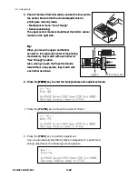
1. Perform test print in self print mode.
(Refer to 2-3-2-(2-1) “Self print mode”.)
2. Visually check the take-up side for ribbon wrinkles.
Since ribbon is taken up stronger on the shorter ribbon path side, wrinkles appear on
the longer path side. During printing the self print patterns, check wrinkles and correct
the ribbon travel as follows:
• If wrinkles are found on the left side (“
a
” in the figure), turn the Ribbon Left-Right
Balance Adjustment Knob (Front) clockwise.
Содержание CLP-621
Страница 1: ...Technical Manual CLP 621 CLP 631 Thermal Transfer Barcode Label Printer JM74961 00F 1 00E 0701...
Страница 2: ...CLP 621 CLP 631 ii Copyright 2007 by CITIZEN SYSTEMS JAPAN CO LTD...
Страница 4: ...CHAPTER 1 SPECIFICATIONS CLP 621 CLP 631...
Страница 13: ...CHAPTER 2 OPERATING PRINCIPLES CLP 621 CLP 631...
Страница 68: ...2 5 Power Supply CLP 621 CLP 631 2 56 N1 N2 N3 N4 BLOCK A BLOCK E BLOCK B BLOCK C BLOCK D 120V type...
Страница 69: ...2 5 Power Supply 2 57 CLP 621 CLP 631 N1 N2 N3 N4 Block A Block B Block C Block E Block D 220 240V type...
Страница 73: ...CHAPTER 3 DISASSEMBLY AND MAINTENANCE CLP 621 CLP 631...
Страница 126: ...CLP 621 CLP 631 CHAPTER 4 TROUBLESHOOTING...
Страница 138: ...CLP 621 CLP 631 CHAPTER 5 PARTS LISTS...
Страница 143: ...Chapter 5 Parts Lists CLP 621 CLP 631 5 6 DRAWING NO 1 General Assembly Rev 0 1 7 8 2 3 4 2 10 11 12 9 5 2 13 14 10...
Страница 163: ...Chapter 5 Parts Lists CLP 621 CLP 631 5 26 DRAWING NO 6 Sensor U Unit Rev 0 4 16 3 2 1 9 10 11 5 8 6 12 7 13 14 15...
Страница 166: ...Chapter 5 Parts Lists CLP 621 CLP 631 5 29 DRAWING NO 7 Control Panel Unit Rev 0 4 3 2 1 5...
Страница 174: ...Chapter 5 Parts Lists CLP 621 CLP 631 5 37 DRAWING NO 9 Ribbon Unit Fan SA2 Rev 0 1 2 4 3 5 6 3...
Страница 177: ...Chapter 5 Parts Lists CLP 621 CLP 631 5 40 DRAWING NO 10 Accessories Rev 0 3 2 4 1...
Страница 179: ...CHAPTER 6 CIRCUIT DIAGRAMS CLP 621 CLP 631...
Страница 208: ...APPENDICES CLP 621 CLP 631...
Страница 211: ...B Mounting Diagrams B Mounting Diagrams B Mounting Diagrams CLP 621 CLP 631 AP 4 AP 4 B 1 Main PCB Main PCB Parts side...
Страница 212: ...B Mounting Diagrams AP 5 CLP 621 CLP 631 Main PCB Solder side...
Страница 213: ...B Mounting Diagrams CLP 621 CLP 631 AP 6 AP 6 B 2 Power Supply PCB 120V 220V B 2 Power Supply PCB 120V 220V...
Страница 214: ...B Mounting Diagrams AP 7 CLP 621 CLP 631 B 3 Ribbon Main PCB Parts side Solder side...
Страница 217: ......


