Chapter 2 Operating Principles
2-4. Interface
CL-E700 series
2-70
(3)
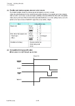
Parallel port status signals when an error occurs
The following table shows the status signal change when an error occurs.
Under the specifications for this bi-directional parallel interface, the parallel port status signals
when an error occurs are, as shown below, partially processed differently than with Compatible
mode used up till now. When bi-directional parallel interface is on in the setting menu, even if a
printer error has occurred, the BUSY signal line is not active (“High”).
Error
Compatible mode
Paper end
Busy:
PError:
Select:
Fault:
L
H
L
H
H
L
H
L
Error other than paper end
• Head open
• Other
Busy:
PError:
Select:
Fault:
L
H
L
unchanged
H
L
H
L
Conditions for Busy
• Receive buffer full
• Data being read
• Error
(4)
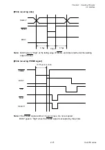
Compatible timing specification
[When power is on] (Timing to go on-line)
BUSY
SELECT
Power On
ACK
Reset
Содержание CL-E700 Series
Страница 1: ...Technical Manual CL E700 series Thermal Transfer Printer...
Страница 5: ...Chapter 1 Specifications 1 1 CL E700 series CHAPTER 1 SPECIFICATIONS...
Страница 15: ...Chapter 2 Operating Principles 2 1 CL E700 series CHAPTER 2 OPERATING PRINCIPLES...
Страница 87: ...Chapter 3 Disassembly and Maintenance 3 1 CL E700 series CHAPTER 3 DISASSEMBLY AND MAINTENANCE...
Страница 151: ...Chapter 4 Troubleshooting 4 1 CL E700 series CHAPTER 4 TROUBLESHOOTING...
Страница 167: ...Chapter 5 Parts Lists CL E700 series CHAPTER 5 PARTS LISTS...
Страница 172: ...Chapter 5 Parts Lists CL E700 series 5 6 DRAWING NO 1 General Assembly Rev 0...
Страница 195: ...Chapter 5 Parts Lists 5 29 CL E700 series DRAWING NO 7 Unit Opepane Rev 0...
Страница 203: ...Chapter 5 Parts Lists 5 37 CL E700 series DRAWING NO 9 SA2 Ribbon Unit Fan Rev 0...
Страница 206: ...Chapter 5 Parts Lists CL E700 series 5 40 DRAWING NO 10 Accessories Rev 0 3 2 4 1 1 1 2 1 3...
Страница 208: ...Chapter 6 Circuit Diagrams 6 1 CL E700 series CHAPTER 6 CIRCUIT DIAGRAMS...
Страница 230: ...Appendices AP 1 CL E700 series APPENDICES...
Страница 232: ...Appendices A Mounting Diagrams AP 3 CL E700 series A Mounting Diagrams A 1 SA Main PCB 1 Parts side...
Страница 233: ...Appendices A Mounting Diagrams CL E700 series AP 4 2 Solder side...

