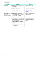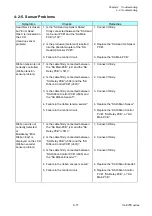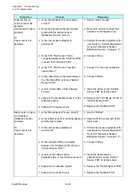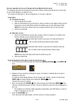
Chapter 4 Troubleshooting
4-2. Troubleshooting
CL-E700 series
4-14
4-2-6. Operation Panel Problems
Symptoms
Checks
Remedies
Nothing is displayed
on the LED
1. Is the “FFC Opepane” firmly connected
between the “SA Main PCB” (J3) and
“SA Opepane PCB”?
2. Is the “FFC Opepane” inserted upside
down?
3. Failure in the “SA Opepane PCB”.
4. Failure in the control circuit.
1. Connect it firmly.
2. Connect it in the right orientation.
3. Replace the “SA Opepane PCB”.
4. Replace the “SA Main PCB”.
No key works.
1. Is the “FFC Opepane” firmly connected
between the “SA Main PCB” (J3) and
“SA Opepane PCB”?
2. Is the “FFC Opepane” inserted upside
down?
3. Failure in the “SA Opepane PCB”.
4. Failure in the control circuit.
1. Connect it firmly.
2. Connect it in the right orientation.
3. Replace the “SA Opepane PCB”.
4. Replace the “SA Main PCB”.
Nothing is displayed
on the LCD
1. Is the printer in standby mode (the LED
lights in green)?
2. Is the “FFC Opepane” firmly connected
between the “SA Main PCB” (J3) and
“SA Opepane PCB”?
3. Is the “FFC Opepane” inserted upside
down?
4. Failure in the “SA Opepane PCB”.
5. Failure in the control circuit.
1. Press any key.
2. Connect it firmly.
3. Connect it in the right orientation.
4. Replace the “SA Opepane PCB”.
5. Replace the “SA Main PCB”.
Содержание CL-E700 Series
Страница 1: ...Technical Manual CL E700 series Thermal Transfer Printer...
Страница 5: ...Chapter 1 Specifications 1 1 CL E700 series CHAPTER 1 SPECIFICATIONS...
Страница 15: ...Chapter 2 Operating Principles 2 1 CL E700 series CHAPTER 2 OPERATING PRINCIPLES...
Страница 87: ...Chapter 3 Disassembly and Maintenance 3 1 CL E700 series CHAPTER 3 DISASSEMBLY AND MAINTENANCE...
Страница 151: ...Chapter 4 Troubleshooting 4 1 CL E700 series CHAPTER 4 TROUBLESHOOTING...
Страница 167: ...Chapter 5 Parts Lists CL E700 series CHAPTER 5 PARTS LISTS...
Страница 172: ...Chapter 5 Parts Lists CL E700 series 5 6 DRAWING NO 1 General Assembly Rev 0...
Страница 195: ...Chapter 5 Parts Lists 5 29 CL E700 series DRAWING NO 7 Unit Opepane Rev 0...
Страница 203: ...Chapter 5 Parts Lists 5 37 CL E700 series DRAWING NO 9 SA2 Ribbon Unit Fan Rev 0...
Страница 206: ...Chapter 5 Parts Lists CL E700 series 5 40 DRAWING NO 10 Accessories Rev 0 3 2 4 1 1 1 2 1 3...
Страница 208: ...Chapter 6 Circuit Diagrams 6 1 CL E700 series CHAPTER 6 CIRCUIT DIAGRAMS...
Страница 230: ...Appendices AP 1 CL E700 series APPENDICES...
Страница 232: ...Appendices A Mounting Diagrams AP 3 CL E700 series A Mounting Diagrams A 1 SA Main PCB 1 Parts side...
Страница 233: ...Appendices A Mounting Diagrams CL E700 series AP 4 2 Solder side...

