Chapter 1 Specifications
1-4. Adjustable Sensors
CL-E700 series
1-10
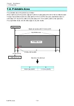
Maximum media width: 118 mm (4.65")
Direction of media feed
2.5 mm
(0.10")
Printable area
Media
H
R
-0.2 to 57.8 mm
(-0.01 to 2.28”)
(Moveable range of the
reflective sensor)
2.8 to 60.8 mm
(0.11 to 2.39”)
(Moveable range of the
transparent sensor)
Media guide
Unprint
able area
Unprint
able area
1-4. Adjustable Sensors
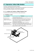
There are two media sensors; the upper sensor (transparent sensor) and the bottom sensor
(reflective sensor). Both upper sensor and bottom sensor are used to detect the labels on the liner
or the U-shaped notches of tag. The bottom sensor is used to detect the black marks on tag. Also,
both sensors are used to detect media end.
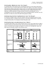
The mechanical adjustable ranges of sensors are as follows.
Upper sensor (transparent sensor):
2.8 to 60.8 mm (0.11 to 2.39”)
Lower sensor (reflective sensor):
-0.2 to 57.8 mm (-0.01 to 2.28”)
Each sensor is adjustable independently. However, when you use the upper sensor (transparent
sensor), the lower sensor (reflective sensor) must be always used together so that they become a
set of sensors.
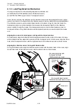
When both sensors are moved to the left end or the right end (center of the printing mechanism),
both sensors coincide for detecting a label or U-shaped notch.
For details about the media sensors, refer to “
2-1-3 Label/Tag Detection Mechanism
H
R
104.0 mm (4.09”)
11.5 mm (0.45”)
Содержание CL-E700 Series
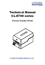
Страница 1: ...Technical Manual CL E700 series Thermal Transfer Printer...
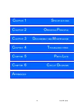
Страница 5: ...Chapter 1 Specifications 1 1 CL E700 series CHAPTER 1 SPECIFICATIONS...
Страница 15: ...Chapter 2 Operating Principles 2 1 CL E700 series CHAPTER 2 OPERATING PRINCIPLES...
Страница 87: ...Chapter 3 Disassembly and Maintenance 3 1 CL E700 series CHAPTER 3 DISASSEMBLY AND MAINTENANCE...
Страница 151: ...Chapter 4 Troubleshooting 4 1 CL E700 series CHAPTER 4 TROUBLESHOOTING...
Страница 167: ...Chapter 5 Parts Lists CL E700 series CHAPTER 5 PARTS LISTS...
Страница 172: ...Chapter 5 Parts Lists CL E700 series 5 6 DRAWING NO 1 General Assembly Rev 0...
Страница 195: ...Chapter 5 Parts Lists 5 29 CL E700 series DRAWING NO 7 Unit Opepane Rev 0...
Страница 203: ...Chapter 5 Parts Lists 5 37 CL E700 series DRAWING NO 9 SA2 Ribbon Unit Fan Rev 0...
Страница 206: ...Chapter 5 Parts Lists CL E700 series 5 40 DRAWING NO 10 Accessories Rev 0 3 2 4 1 1 1 2 1 3...
Страница 208: ...Chapter 6 Circuit Diagrams 6 1 CL E700 series CHAPTER 6 CIRCUIT DIAGRAMS...
Страница 230: ...Appendices AP 1 CL E700 series APPENDICES...
Страница 232: ...Appendices A Mounting Diagrams AP 3 CL E700 series A Mounting Diagrams A 1 SA Main PCB 1 Parts side...
Страница 233: ...Appendices A Mounting Diagrams CL E700 series AP 4 2 Solder side...

