Product Overview 1-45
Functional Overview
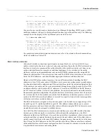
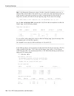
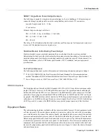
The following example shows only the Temperature Parameters section of the table. In this example,
the measured value at the inlet sensor is 41°C, which falls within the warning range (39°C through
46°C) and therefore is displayed in the Warning column.
Temperature Parameters:
SENSE WARNING NORMAL WARNING CRITICAL SHUTDOWN
------|-------------|------------|-------------|--------------|------------
Inlet 10
39 41(C)
46 64
Air-flow 10 40(C) 70 77 88
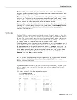
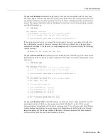
The show environment all command displays an extended report that includes all the information
in the show environment command display, plus the power supply status, the number of intermittent
powerfails (if any) since the system was last powered on, and the measured values at the temperature
sensors and the DC lines. The refresh time indicates that the parameters will be measured again in
29 seconds; any changes to a measurement will not be reflected in the display until at least 40
seconds have elapsed and the current information is refreshed.
7010# show env all
Environmental Statistics
Environmental status as of Fri 11-5-1993 19:10:41
Data is 31 second(s) old, refresh in 29 second(s)
WARNING: Fan has reached CRITICAL level
Power Supply: 550W AC
No Intermittent Powerfails
+12 volts measured at 12.00(V)
+5 volts measured at 5.02(V)
-12 volts measured at -12.05(V)
+24 volts measured at 23.70(V)
Airflow temperature measured at 35(C)
Inlet temperature measured at 26(C)
Fan Shutdown
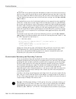
When the system power is on, all six fans in the fan array must be operational. If the system detects
a failed or failing fan, it will display a warning message on the console screen. If the condition is not
corrected within two minutes, the entire system will shut down to avoid an overtemperature
condition and shutdown. The system uses a Hall Effect signal to monitor the six fans in the array.
The current to the fans and the magnetic field generated by the fans’ rotation generates a voltage,
which the system monitors to determine whether or not all of the fans are operating. If the monitored
voltage signal drops below a specified value, the system assumes a fan failure and initiates a fan
shutdown.
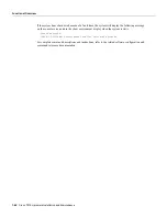
In the following example, the system has detected an out-of-tolerance fan, which it interprets as a
fan failure. The failure message is displayed for two minutes before the system shuts down.
%ENVM-2-FAN: Fan array has failed, shutdown in 2 minutes
Содержание TelePresence Server 7010
Страница 10: ...x Cisco 7010 Hardware Installation and Maintenence ...
Страница 14: ...iv Cisco 7010 Hardware Installation and Maintenance Document Conventions ...
Страница 112: ...2 52 Cisco 7010 Hardware Installation and Maintenance Initial Configuration Information Page ________ ...
Страница 148: ...3 36 Cisco 7010 Hardware Installation and Maintenance Using the Flash Memory Card ...
Страница 158: ...4 10 Cisco 7010 Hardware Installation and Maintenance Troubleshooting the Processor Subsystem ...
Страница 242: ...5 84 Cisco 7010 Hardware Installation and Maintenance Replacing Internal Components ...
Страница 258: ...A 16 Cisco 7010 Hardware Installation and Maintenance MIP Interface Cable Pinouts ...
Страница 270: ...B 12 Cisco 7010 Hardware Installation and Maintenance Interface Processor LEDs ...
Страница 274: ...C 4 Cisco 7000 Hardware Installation and Maintenance ...
Страница 287: ...Index 13 ...

