Troubleshooting the Installation 4-3
Problem Solving with Subsystems
The rest of this chapter describes troubleshooting methods and defines how the router is divided into
subsystems for more efficient problem solving. A description of a normal startup sequence contains
pointers to sections in this chapter that contain troubleshooting procedures for specific components
so that you can determine where your system is having trouble and then troubleshoot that specific
component or subsystem.
Problem Solving with Subsystems
The key to problem solving the system is to try to isolate the problem to a specific subsystem. The
first step in solving startup problems is to compare what the system is doing to what it should be
doing. Since a startup problem is usually attributable to a single component, it is more efficient to
first isolate the problem to a subsystem rather than troubleshoot each component in the system. For
these troubleshooting procedures, consider the following subsystems:
•
Power subsystem—This subsystem comprises the AC-input or DC-input power supply, the
external power cord, and the internal power harness that connects to the backplane.
•
Cooling subsystem—This subsystem comprises the fan tray assembly, which includes the six
individual fans in the array, the fan control board, and the tray itself. All six fans should be
operating whenever the system power is on. The system automatically shuts down if any one or
more of the fans is operating outside the specified range, or shuts down completely. The variable
speed feature allows the fans to operate at a slower speed and provide quieter operation when the
internal chassis temperature is within the normal operating range. If the internal temperature
exceeds a specified temperature, the fan speed increases to move more cooling air through the
chassis. As a result, it may be difficult to determine whether or not the fans are operating in noisy,
air-conditioned rooms. When viewing the chassis from the noninterface processor end, the fan
array spans the right wall of the chassis interior. If you determine that the fans are not operating,
contact a customer service representative immediately. There are no installation adjustments that
you should make if it does not function properly at initial startup.
•
Processor subsystem—This subsystem includes the RP, SP (or SSP), and all interface processors.
The RP contains the system operating software, and the enabled LED on the SP (or SSP) and
each interface processor indicates whether or not the RP was able to initialize it. Remember that
an interface processor that is partially installed in the backplane will cause the system to hang
and crash.
The following sections will help you isolate a problem to one of these subsystems and direct you to
the appropriate troubleshooting section.
Identifying Startup Problems
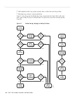
When you start up the router for the first time, you should observe the startup sequence described in
the section “Starting the Router” in the chapter “Installing the Router.” This section contains a more
detailed description of the normal startup sequence and describes the steps to take if the system does
not perform that sequence as expected.
By checking the state of the LEDs on the power supply and processor modules (the RP, SP [or SSP],
and interface processors), you can determine when and where the system failed in the startup
sequence. Use the following descriptions to isolate the problem to a subsystem, then proceed to the
appropriate sections (indicated in each description) to try to resolve the problem.
When you start up the system by turning on the main system power switch on the interface processor
end of the power supply, the following should occur:
Содержание TelePresence Server 7010
Страница 10: ...x Cisco 7010 Hardware Installation and Maintenence ...
Страница 14: ...iv Cisco 7010 Hardware Installation and Maintenance Document Conventions ...
Страница 112: ...2 52 Cisco 7010 Hardware Installation and Maintenance Initial Configuration Information Page ________ ...
Страница 148: ...3 36 Cisco 7010 Hardware Installation and Maintenance Using the Flash Memory Card ...
Страница 158: ...4 10 Cisco 7010 Hardware Installation and Maintenance Troubleshooting the Processor Subsystem ...
Страница 242: ...5 84 Cisco 7010 Hardware Installation and Maintenance Replacing Internal Components ...
Страница 258: ...A 16 Cisco 7010 Hardware Installation and Maintenance MIP Interface Cable Pinouts ...
Страница 270: ...B 12 Cisco 7010 Hardware Installation and Maintenance Interface Processor LEDs ...
Страница 274: ...C 4 Cisco 7000 Hardware Installation and Maintenance ...
Страница 287: ...Index 13 ...

