B-59
Cisco SIP IP Phone Administrator Guide
Appendix B SIP Call Flows
Call Flow Scenarios for Failed Calls
Call from a Cisco SIP IP Phone to a Gateway Acting as an Emergency Proxy
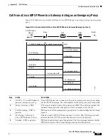
Figure B-22
illustrates a successful call from a Cisco SIP IP phone to a gateway acting as an emergency
proxy.
Figure B-22 A Successful Call from Cisco SIP IP Phone to Gateway (Emergency Proxy)
Step
Action
Description
1.
INVITE—Cisco SIP IP phone to
gateway (emergency proxy)
Cisco SIP IP phone tries to connect to the gateway (emergency proxy) by sending
out the INVITE message. The dial template for the emergency route is matched.
2.
Setup—Gateway to PBX
Call setup is initiated between the gateway and PBX. The call setup includes the
standard transactions that take place as User A attempts to call User B.
3.
Call Proceeding—PBX to
gateway
PBX sends a Call Proceeding message to gateway to acknowledge the Call Setup
request.
4.
100 Trying—Gateway to
Cisco SIP IP phone (User A)
Gateway sends a SIP 100 Trying response to User A. The 100 Trying response
indicates that the INVITE request has been received by the gateway.
5.
Alerting—PBX to gateway
PBX sends an Alert message to the gateway. The Alert message indicates that the
PBX has received a 100 Trying Ringing response from the gateway.
IP
SIP IP Phone
User A
Proxy
2. Setup
3. Call Proceeding
4. 100 Trying
5. Alerting
6. 180 Ringing
7. Connect
8. 200 OK
9. ACK
10. Connect ACK
11. BYE
12. Disconnect
13. Release
14. 200 OK
15. Release Complete
2-way voice path
GW
PBX
User B
62070
1. INVITE (Matches dial template for emergency route)


