The MIC-C/T/P card provides connection for the BATTERY A input, one of the two possible redundant
power supply inputs. It also provides connection for system management serial port, system management
LAN port, and system timing inputs and outputs.
Step 2
Hold the FMEC by the faceplate.
Step 3
Slide the FMEC along the guide rails into the desired FMEC slot or slots.
Step 4
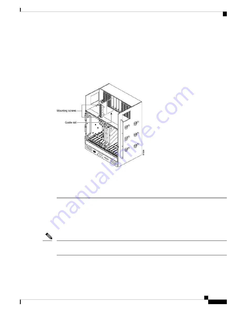
Push the FMEC gently into the connector. The ONS 15454 ETSI FMECs plug into electrical connectors on
the back panel of the shelf when the screws are tightened. The following figure shows FMEC installation.
Figure 39: Installing FMECs on the ONS 15454 ETSI
Step 5
Tighten the screws.
Step 6
Continue with the
NTP-G7 Install the Power and Ground , on page 68
.
Stop. You have completed this procedure.
Power and Ground Description
Ground the equipment according to Telcordia standards or local practices. The following sections describe
power and ground for the ONS 15454 shelves.
For detailed instructions on grounding the ONS 15454 ANSI or ONS 15454 ETSI chassis, refer to the
Electrostatic Discharge and Grounding Guide for Cisco CPT and Cisco ONS Platforms
.
Note
Cisco ONS 15454 Hardware Installation Guide
67
Installing the ONS 15454 M12 (ANSI and ETSI) Shelf
Power and Ground Description
Содержание ONS 15454
Страница 2: ... 2019 Cisco Systems Inc All rights reserved ...
Страница 16: ...Cisco ONS 15454 Hardware Installation Guide xvi Contents ...
Страница 28: ...Cisco ONS 15454 Hardware Installation Guide xxviii Preface Preface ...
Страница 36: ...Cisco ONS 15454 Hardware Installation Guide 6 Overview Cisco ONS 15454 M6 Shelf ...
Страница 510: ...Cisco ONS 15454 Hardware Installation Guide 480 Hardware Specifications Dimensions ...


