


1-15
Cisco ONS 15454 DWDM Installation and Operations Guide, R6.0
August 2005
Chapter 1 Install the Shelf and Common Control Cards
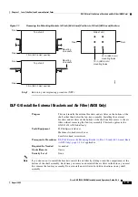
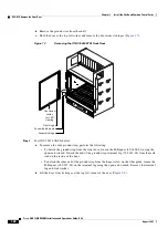
DLP-G6 Mount the Shelf Assembly in a Rack (Two People)
DLP-G6 Mount the Shelf Assembly in a Rack (Two People)
Note
The ONS 15454 ETSI requires 616.5 mm (24.24 inch) minimum of vertical rack space and 25 mm
(1 inch) below the installed shelf assembly to allow air flow to the fan intake. If a second
ONS 15454 ETSI is installed above a shelf assembly, the air ramp between the shelves provides space
for air flow. To ensure that the mounting is secure, use two to four M6 mounting screws for each side of
the shelf assembly. A shelf assembly should be mounted at the bottom of the rack if it is the only unit in
the rack.
Note
The ONS 15454 ANSI must have one inch (25.4 mm) of airspace below the installed shelf assembly to
allow air flow to the fan intake. If a second ONS 15454 is installed underneath a shelf assembly, the air
ramp on top of the bottom shelf assembly provides the desired space. However, if the ONS 15454 is
installed above third-party equipment, you must provide a minimum spacing of one inch (25.4 mm)
between the third-party shelf assembly and the bottom of the ONS 15454. The third-party equipment
must not vent heat upward into the ONS 15454.
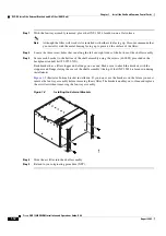
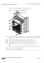
Step 1
Verify that the proper fuse and alarm panel has been installed in the top mounting space. If a fuse and
alarm panel is not present, you must install one according to manufacturer’s instructions:
•
(ETSI only.) Verify that a 100-A fuse panel (30-A fuse per shelf minimum) is installed.
•
(ANSI only.) If you are installing the 15454-SA-ANSI or 15454-SA-HD shelf assembly, a 100-A
fuse panel (30-A fuse per shelf minimum) is required.
•
(ANSI only.) If you are installing the 15454-SA-NEBS3 shelf assembly, a standard 80-A fuse panel
(20-A fuse per shelf minimum) is required.
Step 2
Ensure that the shelf assembly is set for the desired rack size (either 23 inches [584.2 mm] or 19 inches
[482.6 mm]).
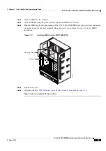
Step 3
Using the hex tool that shipped with the assembly, install the two set screws into the holes that will not
be used to mount the shelf. Let the set screws protrude sufficiently to hold the mounting brackets.
Purpose
This task allows two people to mount the shelf assembly in a rack.
Tools/Equipment
Pinned hex tool
# 2 Phillips screwdriver
ETSI only:
Two M6 x 20 socket set screws
Eight M6 x 20 pan-head Phillips mounting screws
ANSI only:
Two #12-24 x 3/4 set screws (48-1003-XX)
Eight #12-24 x 3/4 pan-head Phillips mounting screws (48-1004-XX,
48-1007-XX)
Prerequisite Procedures
NTP-G1 Unpack and Inspect the Shelf Assembly, page 1-6
Required/As Needed
As needed
Onsite/Remote
Onsite
Security Level
None
Содержание ONS 15454 DWDM
Страница 38: ...Figures xxxviii Cisco ONS 15454 DWDM Installation and Operations Guide R6 0 August 2005 ...
Страница 54: ...Procedures liv Cisco ONS 15454 DWDM Installation and Operations Guide R6 0 August 2005 ...
Страница 64: ... 64 Cisco ONS 15454 DWDM Installation and Operations Guide R6 0 August 2005 Chapter ...


