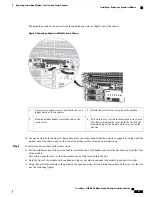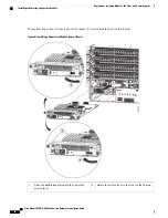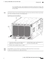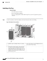
Secure the chassis to the chassis by screwing in two
captive screws and tighten them to 8 in-lb (0.9 N·m)
of torque.
5
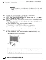
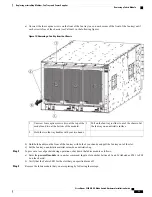
Rotate the ejector lever away from the module.
2
Slide the back end of the module into the open
supervisor slot.
3
d) Rotate the lever all the way to the front of the chassis until it locks in place with a click.
Make sure that the other end of the lever engages behind the front of the slot so that the module fully seats onto the
connectors on the midplane.
e) Screw in the two captive screws to secure the module to the chassis. Tighten the screws to 8 in-lb (0.9 N·m) of torque.
f) Attach the following cables to the module:
•
Console cable
—
Attach to the Console port.
•
Management cable
—
Attach to the Management Ethernet port.
g) Verify that the supervisor module LEDs turn on and appear as follows:
•
The Status (STS) LED is green.
•
The Active (ACT) LED is amber or green.
Installing or Replacing a System Controller Module
The switch can operate with one or two system controller modules installed in the chassis. You can replace
one system controller module while there is another one installed in the chassis.
Statement 1029
—
Blank Faceplates and Cover Panels
Blank faceplates and cover panels serve three important functions: they prevent exposure to hazardous
voltages and currents inside the chassis; they contain electromagnetic interference (EMI) that might disrupt
other equipment; and they direct the flow of cooling air through the chassis. Do not operate the system
unless all cards, faceplates, front covers, and rear covers are in place.
Warning
Statement 1034
—
Backplane Voltage
Hazardous voltage or energy is present on the backplane when the system is operating. Use caution when
servicing
Warning
Cisco Nexus 9504 NX-OS Mode Switch Hardware Installation Guide
63
Replacing or Installing Modules, Fan Trays, and Power Supplies
Installing or Replacing a System Controller Module

