Required Tools and Equipment
•
Voltmeter
Steps
To power on the FCC, follow these steps:
Step 1
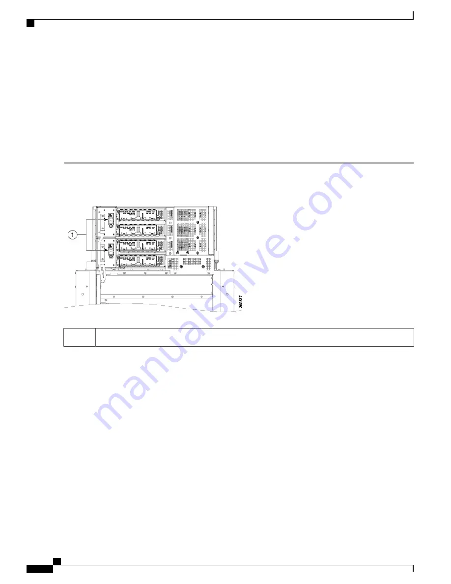
Ensure that the I/O switches on the PCMs on the rear of the FCC are in the OFF position.
Figure 39: PCM I/O Power ON/OFF Switches
I/O power ON/OFF switches
1
Step 2
Verify that none of the Output OK LEDs on the front of the PMs installed in the tray are green (
Step 3
If you have a DC power system installed, follow these steps:
a) Insert the power fuse at the BDFB or power plant to energize power tray 0, PM 0.
b) Measure the voltage at the input terminal block and verify that the DC voltage between the positive and negative
terminals is between
–
48 VDC and
–
60 VDC.
Make sure that the polarity of the DC input power cabling is correct. This is a negative voltage system.
Caution
This is a positive ground system; make sure to connect the positive lead to the +RTN terminal and the
negative lead to the
–
48V terminal.
Caution
c) Verify that the correct Input OK LED on the front of the PM is lit (
Figure 34: AC and DC Power Module Power
d) Repeat Steps
a
through
c
for each of the remaining DC inputs.
e) Continue to Step
5
.
Step 4
If you have an AC power system installed, follow these steps:
Cisco Network Convergence System 6000 Fabric Card Chassis Hardware Installation Guide
58
Installing the Power Components
Powering On the Fabric Card Chassis


