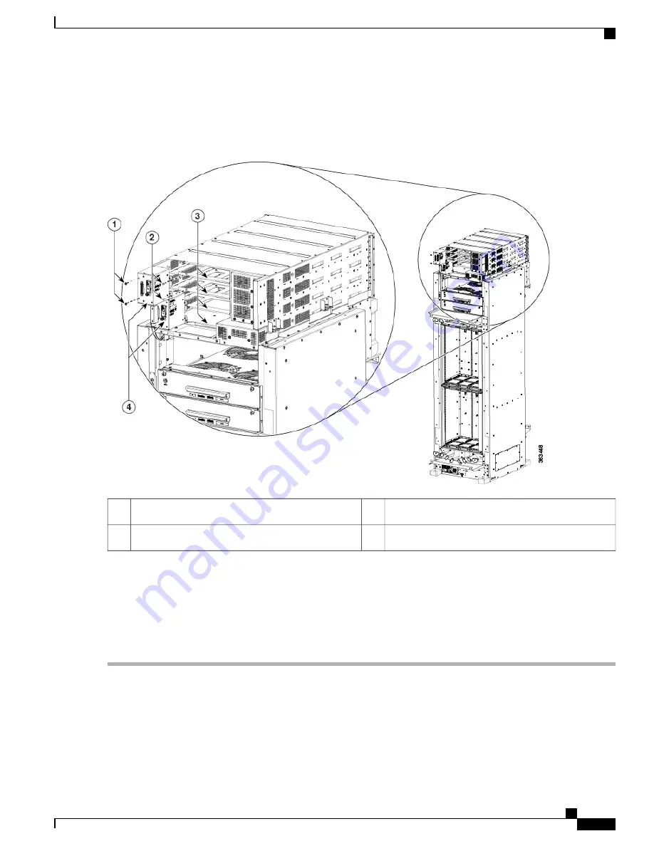
b) Loosen and remove the three 6-32 flat-head screws on the right side flanges of the PCM.
Figure 64: Removing a PCM
Four power trays (2 trays for each PCM)
3
Two 6-32 pan-head screws
1
Two PCMs
4
Two 6-32 flat-head screws
2
Step 6
Using the magnetic screwdriver, attach the replacement PCM.
a) Re-insert and tighten the two 6-32 pan-head screws on the left front face of the PCM.
b) Re-insert and tighten the three 6-32 flat-head screws on the right side flanges of the PCM.
Step 7
Push each power tray in until it engages with the power enclosure connectors.
Step 8
Re-insert and tighten the four pan-head screws for each power tray.
Cisco Network Convergence System 6000 Fabric Card Chassis Hardware Installation Guide
107
Removing and Replacing Chassis Components
Replacing a Power Control Module


