2-3
Cisco Network Convergence System 4000 Series Hardware Installation Guide
Chapter 2 Chassis Overview
About the Cisco NCS 4016 Chassis
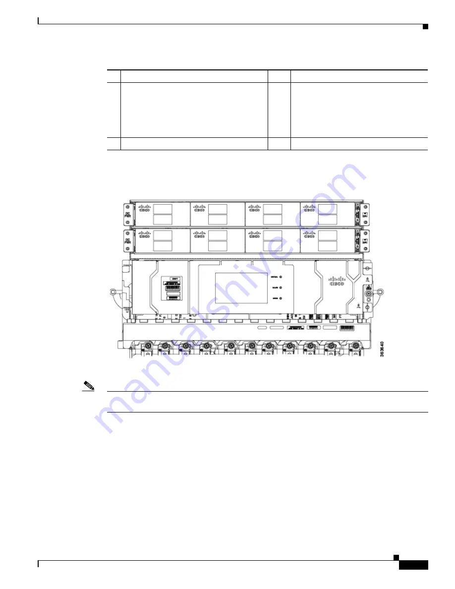
shows the partial chassis view with craft panel.
Figure 2-2
Partial Chassis View with Craft Panel
show partial rear views of the Cisco NCS 4016 chassis.
Note
There are two air outlets on the rear of the chassis. One is at the top behind the ECU and one is below
the bottom fan tray.
1
Power trays (2)
4
Fiber management areas (2)
2
External connection unit (ECU)
•
Craft panel is attached on top of the ECU
(not shown, see
•
Air outlet is on back (not shown, see
)
5
Card cages (2) each containing:
•
8 LC slots
•
2 FC slots (in center)
•
1 RP slot (at side)
3
Fan trays (2)
6
Air inlet


