background image

3


IR510 WPAN Gateway and IR530 WPAN Range Extender Hardware Installation Guide

IR510 Installation

The IR510 WPAN Gateway and IR530 Range Extender can be installed at any height, but best throughput is achieved when all the 
WPAN gateways and WPAN range extenders are mounted at the same height. We recommend installing the devices no higher than 40 
feet to allow support for wireless clients on the ground.

Safety Warning-Hazardous Locations

Before installing this product in a hazardous location, make sure you have read and understood all of the information in the 

Product 

Document of Compliance

 that shipped with the product.

IR510 Installation

This section describes the IR510 WPAN Gateway and includes the following topics:

IR510 Hardware Overview, page 3

IR510 Product IDs and Accessories, page 4

IR510 Cautions and Warnings, page 4

IR510 Hardware Specifications, page 6

IR530 Range Extender Product IDs, page 17

LEDs, page 26

Antenna, page 26

IR510 Hardware Overview

The IR510 operates within a wireless mesh network, providing intelligent control over Cisco Resilient Mesh Endpoints (RMEs) devices 
that use Serial (RS232/RS485), USB (LS/FS/HS), or Fast Ethernet (10/100 Fast Ethernet) ports. Additionally, the gateway employs GPS 
for time synchronization and location tracking.

The IR510 works with the CGR1000 series of routers, primarily in the electrical grid to provide a low cost, low power, small size DA 
solution. The IR510 Gateway (

Figure 1 IR510 in IP30 Enclosure, page 7

) comes within a ruggedized IP30 enclosure. The enclosure allows 

installation of IR510 within outdoor cabinets.

For more details on product features, applications and accessories, refer to:

Cisco IR510 WPAN Industrial Router Data Sheet

Содержание IR510

Страница 1: ...es hardware and software specifications lists Cautions and Warnings to note before physically installing the systems Provides steps for unpacking the system and physically installing the system and details on how to monitor the systems such as LEDs IR530 Series Resilient Mesh Range Extender Installation page 16 Configuring IR510 and IR530 Systems page 26 Provides details on configuring and monitor...

Страница 2: ... causes of interference that can reduce throughput and range Follow these basic guidelines to ensure the best possible performance For information on planning and initially configuring your Cisco Resilient Mesh network refer to the Cisco Wireless Mesh Access Points Design and Deployment Guide on Cisco com Review the FCC guidelines for installing and operating outdoor wireless LAN devices at https ...

Страница 3: ...view page 3 IR510 Product IDs and Accessories page 4 IR510 Cautions and Warnings page 4 IR510 Hardware Specifications page 6 IR530 Range Extender Product IDs page 17 LEDs page 26 Antenna page 26 IR510 Hardware Overview The IR510 operates within a wireless mesh network providing intelligent control over Cisco Resilient Mesh Endpoints RMEs devices that use Serial RS232 RS485 USB LS FS HS or Fast Eth...

Страница 4: ...antenna near overhead power lines or other electric light or power circuits or where it can come into contact with such circuits When installing the antenna take extreme care not to come into contact with such circuits because they may cause serious injury or death For proper installation and grounding of the antenna please refer to national and local codes for example U S NFPA 70 National Electri...

Страница 5: ...installations Be sure that power is removed from the switch and cannot be accidentally be turned on or verify that the area is nonhazardous before proceeding Statement 1070 WARNING Explosion Hazard Do not connect or disconnect wiring while the field side power is on an electrical arc can occur This could cause an explosion in hazardous location installations Be sure that power is removed or that t...

Страница 6: ...otify your sales representative Package Contents IR510 Grounding lug with 2 screws Mechanical kit with 2 mounting brackets and 4 screws Pointer cards for product and compliance documentation IR510 Hardware Specifications IMPORTANT Be sure to review both the IR510 Cautions and Warnings page 4 and Additional Information for Installation in a Hazardous Environment IR510 Only page 4 before mounting th...

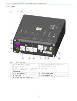
Страница 7: ... 4 on page 8 7 Console port RJ45 10 100 Fast Ethernet port 2 Ground connection point 8 DC power and alarm connector 3 USB 2 0 port covered by Caution panel The USB port has access to RS232 RJ45 serial ports and Fast Ethernet ports 9 Reset button 4 10 100 Fast Ethernet port 10 WPAN antenna connector 5 RS232 DTE port 11 GPS antenna connector 6 RS232 DCE or RJ485 DCE selectable port ...

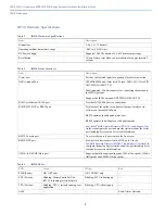
Страница 8: ...ser the option to configure either port interface via software on the same RJ45 port RS232 operates in full duplex mode port RS485 operates in half duplex or full duplex mode Use the IoT Field Network Director FND 4 1 and higher User Guide to configure the port and provide statistics about the serial port including bytes sent and received information RS232 Console port To access the console port r...

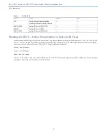
Страница 9: ... minimum clearances see Figures Contact your Cisco Technical Assistance Centre TAC if tighter spacings are required Sides 1 0 in 25 4 mm Front 1 0 in 25 4 mm Rear 1 0 in 25 4 mm Top 1 0 in 25 4 mm the device can be installed in a 1 25 tall slot but the mounting surface must have thermal conductive properties equivalent to or better then 302 stainless steel 16 3 W m k FE Solid Ethernet Link Establi...

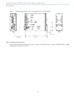
Страница 10: ...10 IR510 WPAN Gateway and IR530 WPAN Range Extender Hardware Installation Guide IR510 Installation Figure 2 IR510 Mounting Clearance Shown for Optimum Airflow Rack Mount ...

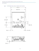
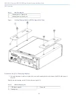
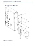
Страница 11: ...R510 Installation Figure 3 IR510 Mounting Clearance Shown for Optimum Airflow DIN Rail Mount IR510 Mounting Options There are two mounting options for IR510 Rack Figure 4 on page 12 and DIN Rail Figure 5 on page 13 Mounting hardware is shipped in the IR510 Accessory Kit 53 100793 01 ...

Страница 12: ...ting Brackets 1 Use a ratcheting torque screwdriver to tighten the 4 screws and 2 mounting brackets to the bottom of the IR510 with a torque of 8 11in lbs Note For rear rack mounting use the 8 32 holes with a max depth of 25 Table 5 Rack Mounting Kit 1 Mounting Screws Quantity of 4 2 Mounting Brackets Quantity of 2 Table 6 DIN Rail Mounting Kit 1 DIN bracket assembly 3 Release tab 2 Spring Cover ...

Страница 13: ...13 IR510 WPAN Gateway and IR530 WPAN Range Extender Hardware Installation Guide IR510 Installation Figure 5 Attaching DIN Rail Mounting IR510 Hardware Installation Steps for DIN Rail Kit ...

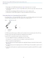
Страница 14: ...6 Grounding Accessory Kit CAUTION To make sure that the equipment is reliably connected to earth ground follow the steps below and use 14 to 16 AWG wire CAUTION Use at least a 4 mm2 conductor to connect the two external ground screws to the IR510 To ground the IR510 to earth ground by using the 2 ground screws follow these steps 5 Use a wire stripping tool to strip the 14 to 16 AWG ground wire to ...

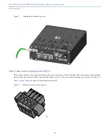
Страница 15: ... IR510 requires DC power You connect the DC power and alarm connections to the IR510 through the Power and Alarm Connector found on the far right front panel of the IR510 above the Reset Button Figure 7 The power connector labeling is on the connector Figure 8 Table 7 on page 16 shows the power and alarm connectors for IR510 Figure 8 IR510 Power and Alarm Connector I 391216 ...

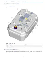
Страница 16: ...ess mesh network providing longer reach between WPAN endpoints and other WPAN networks There are two IR500 Mesh Range Extender products in the IR500 family The IR529 and IR530 IR530 represents a high performance new generation of the Cisco RF Mesh range extender The IR530 Range Extenders take full advantage of Cisco networking expertise in IPv6 security It provides an open high performance RF mesh...

Страница 17: ...igure 9 IR530 Bottom View IR530 Range Extender Product IDs Note You can order the IR530 with a single or dual antenna and a battery For IR530 part numbers for systems with batteries and the latest regional support refer to the data sheet Table 8 IR530 Components 1 Antenna port 4 Ground 2 System LED 5 Vent 3 AC input 6 Console Port Access ...

Страница 18: ...from overheating do not operate it in an area that exceeds the maximum recommended ambient temperature of 60C Statement 1047 WARNING Do not locate the antenna near overhead power lines or other electric light or power circuits or where it can come into contact with such circuits When installing the antenna take extreme care not to come into contact with such circuits because they may cause serious...

Страница 19: ... consumption or dissipation Normal operation 6W max With BBU charging 23W max IEEE 802 15 4 WPAN IEEE 802 15 4g e v Frequency support 902 928 MHz and subset of it to comply with country s regulations North America ISM 902 928 MHz Australia 915 928 MHz Brazil 902 907 5 915 928 MHz Spread spectrum technology Frequency hopping OFDM 31 channels 800kHz channel spacing 2FSK 64 channels 400kHz channel sp...

Страница 20: ...ou can mount the IR530 on a pole using a mounting bracket To attach the mounting bracket to the pole see Figure 10 To attach the IR30 to the mounting bracket see Figure 11 IR530 Range Extender Orientation When mounting the IR530 Range Extender on a pole ensure that the extender is oriented with the antenna pointing downwards see Figure 11 Note After you attach the IR530 to the mounting bracket you...

Страница 21: ...nder Installation Figure 10 Attaching IR530 Mounting Bracket to Pole Figure 11 Attaching the IR530 Range Extender to the Pole Mounting Bracket Table 11 Mounting Kit Components 1 Pole 4 Washer 2 U bolt part number 62 2766 01 5 Spring loaded washer 3 Pole mounting bracket part number 700 45850 01 6 Nut 1 2 3 4 5 6 391281 ...

Страница 22: ...ccessory kit that ships with the IR530 includes one tabular ground lug and two ground screws to provide protective ground for the IR530 Figure 12 You must provide the 6 AWG ground wire It is not included in the kit Note You must ground the IR530 before you connect power cables Table 12 IR530 Mounting Components 1 Screws 4 to attach IR530 to mounting bracket 2 Mounting holes 4 ...

Страница 23: ...und wire to the grounding lug Figure 13 Figure 13 Crimping the Ground Lug 2 Connect the grounding lug to the IR530 WPAN Range Extender ground connection point using the supplied screws Figure 14 Tighten the screws to 10 to 12 foot pounds of torque 3 If necessary strip the other end of the ground wire and connect it to a reliable earth ground such as a grounding rod or an appropriate grounding poin...

Страница 24: ...you install the unit outdoors or in a wet or damp location the AC branch circuit that powers the unit should have ground fault protection GFCI as required by Article 210 of the NEC If the power cord goes through a metal cover a bushing should be installed to prevent fraying of the cord When using a strain relief bushing you should follow these recommendations Use properly sized parts Use bushings ...

Страница 25: ...ender end of the cable first When removing the AC power connector always disconnect the IR530 Range Extender end of the cable last 2 Verify that the unit is grounded as described in the Grounding the WPAN Range Extender section on page 2 24 3 Turn off power to the AC power source at the designated circuits 4 Align the notch in the IR530 Range Extender power cable connector with the key in the rang...

Страница 26: ...e 4 2 x Cisco Connected Grid WPAN Module for CGR 1000 Series Installation and Cisco Resilient Mesh Configuration Guide Cisco IOS LED Name Definition State RSSI Measure of power present in the received radio signal Yellow Off Green Off RSSI less than 105 dBm Yellow On Green Off RSSI is 105 to 95 dBm Yellow Off Green Slow Blink RSSI is 95 to 75 dBm Yellow Off Green Fast Blink RSSI is 75 to 60 dBm Ye...

Страница 27: ...entation Connected Grid Module CGM WPAN OFDM FCC Module Cisco IOS Release Notes for Cisco Resilient Mesh Release 5 7 27 Release Notes for Cisco Resilient Mesh Release 5 6 21 Cisco 1120 Connected Grid Router Hardware Installation Guide Cisco 1240 Connected Grid Router Hardware Installation Guide ...

Страница 28: ...28 IR510 WPAN Gateway and IR530 WPAN Range Extender Hardware Installation Guide Related Documentation ...

Отзывы: