background image

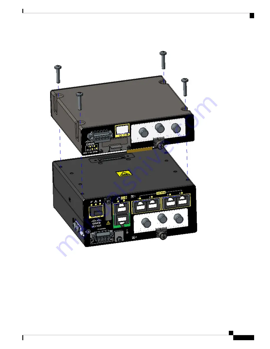
Figure 27: Mounting the Expansion Module

Step 3

Tighten the screws to a torque of 13-15 in. lbs (1.5-1.7) newton meter). When complete, the two devices form a single
assembly as shown in

Figure 28: Completed Assembly, on page 54

.

IR1101 Industrial Integrated Services Router Hardware Installation Guide

53

Installing the IRM-1100 Expansion Module

Installing the Expansion Module

Содержание IR1101

Страница 1: ...ter Hardware Installation Guide First Published 2018 07 04 Last Modified 2019 12 04 Americas Headquarters Cisco Systems Inc 170 West Tasman Drive San Jose CA 95134 1706 USA http www cisco com Tel 408 526 4000 800 553 NETS 6387 Fax 408 527 0883 ...

Страница 2: ... 2018 2019 Cisco Systems Inc All rights reserved ...

Страница 3: ...ct Overview 9 General Description 9 SKU Information 10 Cisco IR1101 Series Platform Features 11 Cisco IR1101 Base Router 11 Cisco IRM 1100 SPMI Expansion Module 13 Cisco IR 1100 SP Expansion Module 17 Cisco Pluggable Module 17 mSATA Module 18 Front Panel Icons and LEDs 19 Memory 21 Reset Button 21 Supported Cisco Antennas and Antenna Accessories 21 Modem Support 21 Power Supply 23 IR1101 Industria...

Страница 4: ...tion and Installation 43 C H A P T E R 4 Antenna Selection and Installation 43 Antenna Installation Best Practices 43 Supported Antennas for the IR1101 45 Cellular 2G 3G 4G Antennas 45 GPS GNSS Antennas 46 Supported RF Cables for the IR1101 47 Cellular Antenna Extension Bases 49 Accessories 49 Installing the IRM 1100 Expansion Module 51 C H A P T E R 5 Installing the IRM 1100 Expansion Module 51 I...

Страница 5: ...65 Preventing Damage to the Router 65 Connecting a PC Server or Workstation 65 GUI Centric Task Template 66 Connecting to DC Power 66 Plugs and Pin Outs 67 Wiring the DC Power 67 Serial Port Cable 69 DB9 Adapter Side 70 RJ 45 Adapter Side 71 Verifying Connections 76 Technical Specifications 77 C H A P T E R 7 Technical Specifications 77 Router Specifications 77 IR1101 Base Unit 77 IRM 1100 Expansi...

Страница 6: ...IR1101 Industrial Integrated Services Router Hardware Installation Guide vi Contents ...

Страница 7: ...e NOTE Means reader take note Notes contain helpful suggestions or references to additional information and material CAUTION This symbol means reader be careful In this situation you might do something that could result in equipment damage or loss of data TIP Means the following information will help you solve a problem The tip information might not be troubleshooting or even an action but could b...

Страница 8: ...ttelemiseen liittyvät riskit ja tutustu onnettomuuksien yleisiin ehkäisytapoihin Turvallisuusvaroitusten käännökset löytyvät laitteen mukana toimitettujen käännettyj turvallisuusvaroitusten joukosta varoitusten lopussa näkyvien lausuntonumeroiden avulla SÄILYTÄ NÄMÄ OHJEET Varoitus IMPORTANTES INFORMATIONS DE SÉCURITÉ Ce symbole d avertissement indique un danger Vous vous trouvez dans une situatio...

Страница 9: ...quer equipamento tenha conhecimento dos perigos env no manuseio de circuitos elétricos e familiarize se com as práticas habituais de prevenção de acide Utilize o número da instrução fornecido ao final de cada aviso para localizar sua tradução nos aviso segurança traduzidos que acompanham este dispositivo GUARDE ESTAS INSTRUÇÕES Aviso INSTRUCCIONES IMPORTANTES DE SEGURIDAD Este símbolo de aviso ind...

Страница 10: ...zidos que acompanham dispositivo GUARDE ESTAS INSTRUÇÕES Aviso VIGTIGE SIKKERHEDSANVISNINGER Dette advarselssymbol betyder fare Du befinder dig i en situation med risiko for legemesbeskadigelse du begynder arbejde på udstyr skal du være opmærksom på de involverede risici der er ved elektriske kredsløb og du skal sætte dig ind i standardprocedurer til undgåelse af ulykker Brug erklæringsnumm efter ...

Страница 11: ...IR1101 Industrial Integrated Services Router Hardware Installation Guide 5 Preface Safety Warnings ...

Страница 12: ...fied by Electrical Appliance and Material Safety Law that have PSE shown on the code is not limited to CISCO designated products Statement 371 Warning Read the wall mounting instructions carefully before beginning installation Failure to use the correct hardware or to follow the correct procedures could result in a hazardous situation to people and damage to the system Statement 378 Warning Read t...

Страница 13: ...nnected last Statement 1046 Warning Do not locate the antenna near overhead power lines or other electric light or power circuits or where it can come into contact with such circuits When installing the antenna take extreme care not to come into contact with such circuits because they may cause serious injury or death For proper installation and grounding of the antenna please refer to national an...

Страница 14: ...es within a specific document Use the Full Reader Search window to search multiple PDF files simultaneously and to change case sensitivity and other options Adobe Reader s online help has more information about how to search PDF documents Obtaining Documentation and Submitting a Service Request For information on obtaining documentation submitting a service request and gathering additional informa...

Страница 15: ...OTE Prior to installing this device read the Regulatory Compliance and Safety Information General Description The Cisco IR1101 Industrial Integrated Services Router is a next generation modular industrial router which has a base module with additional Pluggable Modules that can be added The Pluggable Module provides the flexibility of adding different interfaces to the IR1101 platform for example ...

Страница 16: ... mSATA SSD Slot IRM 1100 SPMI Expansion Module with 1 GE SFP and1 Pluggable Module IRM 1100 SP 100 GB mSATA SSD IR1100 SSD 100G Optional AC power adapter with 110 220V AC and 88 300V DC input Temperature 40C to 60C PWR IE50W AC Din rail kit and mounting screws for horizontal and vertical mounting IR1101 DINRAIL Din rail kit for the Expansion Module IRM 1100 DINRAIL Wall mount kit IR1101 WALLMNT IR...

Страница 17: ...er copper wiring standards of 10Base T 100Base TX and 1000Base T SFP port will support 1000Base X or 100Base FX Fiber Ethernet standard SFP see the supported list of SFP s here SFP Module page 26 LAN Ports 4x RJ45 10 100 Fast Ethernet Serial Port 1 x RJ45 RS232 Port DTE USB Ports 1x USB 2 0 Type A Host Port 1x USB 2 0 mini USB Type B console port Compliance Class A EMC or better IP30 compliant whe...

Страница 18: ...hows the IR1101 Base Module Front Figure 3 Cisco IR1101 Integrated Services Router with USB covers in place Details Item USB 2 0 Port Cover 1 Mini USB Console Cover 2 IR1101 Industrial Integrated Services Router Hardware Installation Guide 12 Product Overview Cisco IR1101 Base Router ...

Страница 19: ...wer and Alarm Input 7 USB 2 0 2 Mini USB Console 8 RJ45 GE WAN 3 Reset Button 9 Serial Port 4 Pluggable Module 1 0 FE LAN Ports 1 4 5 Cisco IRM 1100 SPMI Expansion Module Figure 5 shows the IR 1100 SPMI Expansion Module IR1101 Industrial Integrated Services Router Hardware Installation Guide 13 Product Overview Cisco IRM 1100 SPMI Expansion Module ...

Страница 20: ...1100 SPMI 1 GE SFP see the supported list of SFP s here SFP Module page 26 1 Pluggable slot 1 Digital I O connector 1 mSATA SSD slot Figure 6 IR 1100 SPMI Expansion Module Details IR1101 Industrial Integrated Services Router Hardware Installation Guide 14 Product Overview Cisco IRM 1100 SPMI Expansion Module ...

Страница 21: ...ower 3 3V to 60V max 150mA of current allowed at high voltage applied usually used to energize something For example solenoid light Figure 7 shows the connector Digital I O is only supported on IOS XE version 16 12 1 and above Note The default state of the Digital I O is input the open collector is open off Note Figure 7 Digital I O connector The pinouts for the Digital I O are described in Table ...

Страница 22: ...t Maximum Minimum Specification No external voltage applied Volts 2 5 Output Voltage High No external voltage applied Volts 0 4 Output Voltage Low Ohms 3 3K 1 3 3K 1 Internal Pull up Resistance Volts 3 Internal Pull up Voltage External resistance required to limit current to 200mA Volts 60 3 3 External Pull up Voltage mA 200 Sink Current Common features of the Digital I O are Withstands up to 60V ...

Страница 23: ...ithout the Digital I O and mSATA components The following lists the hardware platform features for the Cisco IR 1100 SP 1 GE SFP see the supported list of SFP s here SFP Module page 26 1 Pluggable slot Cisco Pluggable Module The Pluggable Module provides the flexibility of adding different interfaces to the IR1101 platform for example a cellular module Pluggable LTE Module Highlights of the LTE Pl...

Страница 24: ...at enables more effective Serial ATA SATA integration in small form factor drives roughly the size of a business card such as solid state disks SSDs The mSATA Pluggable Module plugs into the IR 1100 SPMI Expansion Module Figure 10 shows the mSATA Pluggable Module IR1101 Industrial Integrated Services Router Hardware Installation Guide 18 Product Overview mSATA Module ...

Страница 25: ...shows the Icons without associated LEDs and their descriptions Table 6 Icons with LEDs Description Activity Icon Description Activity Icon Alarm Alarm Input Status Off Normal operation Red Alarm State on the Alarm Input System Power and System Status Off No power Green Steady on Normal operation Green Flashing Boot up phase or in ROM Monitor mode Amber Steady on Power is OK but possible internal f...

Страница 26: ...O Off InactiveSolid Yellow Active mSATA Storage Off Not powered on or no activityFlashing Green mSATA being accessed Table 7 Icons only Description Icon Description Icon USB 2 0 Type A Port for Storage and Networking USB 2 0 Console Mini B Connector Reset Button Grounding point located on side of device DC Power Return DC Power Input 12V to 48V Alarm IN Alarm Return Warning Serial Ports Expansion ...

Страница 27: ...able Module For detailed information about Cisco Antennas for the Industrial Routers please refer to the following guide Cisco Industrial Routers and Industrial Wireless Access Points Antenna Guide http www cisco com c en us td docs routers connectedgrid antennas installing combined industrial routers and industrial wireless antenna guide html Modem Support The Cisco IR1101 wireless Pluggable Modu...

Страница 28: ...carriers that operate FDD LTE 700 MHz band 12 700 MHz band 29 800 MHz band 20 850 MHz band 5 CLR 850 MHz bands 26 Low 900 MHz band 8 1800 MHz band 3 1900 MHz band 2 1900 MHz PCS band 25 1700 MHz and 2100 MHz band 4 AWS 2100 MHz band 1 2300 MHz band 30 or 2600 MHz band 7 networks The multimode Cisco LTE Advanced 3 0 NIMs are backward compatible with Universal Mobile Telecommunications Service UMTS ...

Страница 29: ... the location and values of the power connector Figure 11 Power Connector Pin Outs Description Name Pin Number DC Power Positive Input DC In 1 DC Power Return DC In 2 Alarm Common ALM REF 3 Alarm Input ALM IN 4 RJ45 Ports The IR1101 supports one ISOLATED RS232 port which conforms to EIA 561 standard The RJ45 pinouts are shown in Figure 12 Figure 12 S0 Characteristics The RS232 port is a DTE and it...

Страница 30: ...nectors allow copper connections You can use any combination of the supported SFP modules listed in the table that follows Note The IR1101 is designed to operate in the Industrial temperature range 40C to 85C internal component temperature range and therefore cannot support commercial rated SFPs Table 11 Supported Gigabit SFPs DOM Industrial 40C to 85C Extended 5C to 85C Commercial 0C to 70C Fiber...

Страница 31: ...S SMF 10 km GLC FE 100LX RGD For the most up to date list of supported SFP models for Cisco Industrial Ethernet switches see http www cisco com en US docs interfaces_modules transceiver_modules compatibility matrix OL_6981 html wp138176 IR1101 Industrial Integrated Services Router Hardware Installation Guide 25 Product Overview SFP Module ...

Страница 32: ...IR1101 Industrial Integrated Services Router Hardware Installation Guide 26 Product Overview SFP Module ...

Страница 33: ...ARNING Do not locate the antenna near overhead power lines or other electric light or power circuits or where it can come into contact with such circuits When installing the antenna take extreme care not to come into contact with such circuits because they may cause serious injury or death For proper installation and grounding of the antenna please refer to national and local codes for example U S...

Страница 34: ...er for chassis grounding Wire for connecting the chassis to an earth ground Ethernet cables for connecting to the Fast Ethernet FE WAN and LAN ports Ratcheting torque flathead screwdriver that exerts up to 15 in lb 1 69 N m of pressure A number 2 Phillips screwdriver Ethernet Devices Identify the Ethernet devices that you will connect to the router hub servers and workstations or PCs Ensure that e...

Страница 35: ... use the correct hardware or to follow the correct procedures could result in a hazardous situation to people and damage to the system Statement 378 WARNING A minimum of 1 inch clearance is required on all sides of the product when mounting to allow for proper air flow The wall mounting kit contains the following Mounting brackets x2 Mounting screws x4 To mount the router on a wall or other flat s...

Страница 36: ... with the attached brackets in a proper wall structure to carry the weight of the device See Figure 14 Wall Floor mounting hole dimensions with mounting brackets attached on page 31 and Figure 15 Wall Floor mounting clearance and overall dimensions with mounting brackets attached on page 32 for the dimensions of the mounting holes with the brackets attached to the router IR1101 Industrial Integrat...

Страница 37: ...attached Four 10 32 screws are recommended when mounting the unit with these brackets attached to the neighboring surface Note IR1101 Industrial Integrated Services Router Hardware Installation Guide 31 Installing the Router Mounting on a Wall Table or Other Flat Surface ...

Страница 38: ... attached Step 5 Route the cables so that they do not put a strain on the connectors or mounting hardware Installing a DIN Rail The DIN Rail kit is ordered separately IR1101 Industrial Integrated Services Router Hardware Installation Guide 32 Installing the Router Installing a DIN Rail ...

Страница 39: ...1 First attach the DIN rail bracket to the back of the router The DIN rail bracket mounts in two different ways depending on the orientation you wish to use See the following two figures for vertical orientation and for horizontal orientation Figure 16 Attaching the DIN Rail Bracket for vertical mounting Position the router with the ground lug facing down for vertical mounting Note IR1101 Industri...

Страница 40: ...les 3 that correspond to your orientation Then use 13 15 in lbs of torque to screw the bracket onto the router Step 3 Once the bracket is attached to the router it can be mounted onto the DIN Rail Attaching the Bracket onto the DIN Rail To attach the Cisco IR101 with the bracket to a DIN rail follow these steps Refer to the following figure for details IR1101 Industrial Integrated Services Router ...

Страница 41: ...nst the lower section of DIN rail 2 and then rotate the router so that the top hook of the DIN clip 1 clamps to the top section of DIN rail 2 Step 3 To remove the router from the DIN Rail simply reverse the procedure What to do next The procedure to attach the unit to the rail is the same with both orientations Note IR1101 Industrial Integrated Services Router Hardware Installation Guide 35 Instal...

Страница 42: ...y installed ground conductor Contact the appropriate electrical inspection authority or an electrician if you are uncertain that suitable grounding is available Statement 1024 CAUTION Cable distribution system should be grounded earthed in accordance with ANSI NFPA 70 the National Electrical Code NEC in particular Section 820 93 Grounding of Outer Conductive Shield of a Coaxial Cable To install th...

Страница 43: ...ministrative access as required for your installation Pluggable Module The Pluggable Module provides the IR1101 with a number of different configuration options In this section the modular cellular modem Pluggable Module remove and replace option is shown The IR1101 may have a blank plate covering the Pluggable Module slot This will need to be removed prior to installing the cellular modem module ...

Страница 44: ...by inserting the micro sims applicable for your modems into the device Remove the screw 1 holding the access plate in place that covers the sim slots It is located on the side of the module as shown in IR1101 Industrial Integrated Services Router Hardware Installation Guide 38 Installing the Router Pluggable Module ...

Страница 45: ... Sim Installation on page 39 Make note of the proper slot number and sim orientation Figure 22 Sim Installation Description Item Micro SIMs 1 SIM 0 towards the device 2 IR1101 Industrial Integrated Services Router Hardware Installation Guide 39 Installing the Router Pluggable Module ...

Страница 46: ... USB cover is properly installed Place the USB cover 1 with the plug indentation against the USB port 2 The half circle of the USB cover fits behind the latch lock screw See Figure 23 USB Port Cover Installation on page 40 for details Figure 23 USB Port Cover Installation Step 7 Tighten the latch lock screw to a torque of 2 8 to 3 8 inch lbs 0 3 to 0 4 newton meter Refer to Figure 24 USB Cover Fin...

Страница 47: ...2 The latch lock screw 1 aligns with the screw hole 2 on the front of the device Push the Pluggable Module all the way into the device until you feel it seat and then torque the latch lock screw 8 10 inch pound 0 9 to 1 1 newton meter IR1101 Industrial Integrated Services Router Hardware Installation Guide 41 Installing the Router Pluggable Module ...

Страница 48: ...for each antenna type be sure to consult the antenna documentation for proper orientation and torque to install them Step 10 If no antennas are being installed on a port make sure the caps are installed on the connector IR1101 Industrial Integrated Services Router Hardware Installation Guide 42 Installing the Router Pluggable Module ...

Страница 49: ...station tower away from obstructions and with an unobstructed view of the cellular tower Because antennas transmit and receive radio signals over the air the signal propagation and antenna performance may be adversely affected by the surrounding environment including physical obstructions Radio frequency RF interference may also occur between wireless systems located close to each other especially...

Страница 50: ...d MIMO performance Spacing Main and Aux LTE antennas less than 8 5 inches may result in significantly reduced MIMO performance Spacing antennas too close to each other e g 3 inches results in antennas significantly detuning from their original designed performance due to antenna coupling Wherever possible mount the IR1101 router with the pluggable LTE module and antenna where the cellular base sta...

Страница 51: ...r 2G 3G 4G LTE and one port for GPS 4G LTE 698 960 1448 1511 1710 2400 2500 2700 MHz 2 6 dBi typical 3 8 dBi max 698 960 MHz 3 8 dBi typical 4 3 dBi max 1448 1511 MHz 4 6 dBi typical 5 5 dBi max 1710 2700 MHz No GPS element and no WiFi 2 x 4G LTE TNC m Cisco Cellular 2 in 1 Vehicle Mount and Fixed Infrastructure Antenna ANT 2 4G2 O Two port 2G 3G 4G antenna with two elements This dual port LTE ant...

Страница 52: ... a variety of other electromagnetic considerations installing the antenna directly on the chassis is not always recommended GPS GNSS Antennas Antenna Frequency Band Support and Gain RF Connectors Part Number Description Active GPS antenna 4 0 dBi min at Zenith 1575 42 MHz plus 25 dB amplifier gain Right angle TNC m Cisco GPS Antenna ANT GPS OUT TNC Active GPS antenna integrated 15 LMR 100 cable wi...

Страница 53: ...GHz0 8 dB 5 8 GHz N m STR to N m RALMR 400 5 foot RF cableType outdoor DB direct burial AIR CAB005LL N 0 2 dB 0 7 GHz 0 3 dB 1 0 GHz 0 4 dB 1 7 GHz 0 5 dB 2 4 GHz 0 8 dB 5 8 GHz N m STR to N m RALMR 400 5 foot RF cableType outdoor DB direct burial CAB L400 5 N N 0 2 dB 0 7 GHz0 3 dB 1 0 GHz0 4 dB 1 7 GHz0 5 dB 2 4 GHz0 8 dB 5 8 GHz N m STR to N m STR LMR 400 5 foot RF cable Type outdoor DB direct ...

Страница 54: ...validate whether the cable allows sufficient signal to noise ratio to or from cell tower 4G CAB LMR240 50 1 9 dB 0 7 GHz 2 3 dB 1 0 GHz 3 1 dB 1 7 GHz 3 8 dB 2 4 GHz TNC m RA to TNC f STRLMR 400 50 foot RF cable Type Plenum 4G CAB ULL 50 5 5 dB 0 7 GHz 6 7 dB 1 0 GHz 8 8 dB 1 7 GHz 10 7 dB 2 4 GHz TNC m RA to TNC f STRLMR 240 75 foot RF cable Type PlenumNote The cable is not recommended for high t...

Страница 55: ...8 Cisco Lightning Arrestors on page 49 Table 19 Cisco Coaxial Adapters on page 49 Table 18 Cisco Lightning Arrestors Arrestor Type and Frequency Range MHz Connectors Type Cisco PID DC to 6000 MHz GDT typeSupports active GNSS antennas passes DC N m STR to N f STR CGR LA NM NF 698 to 2700 MHzHigh power ultra low shunt impedance HPF typeDoes not pass DC no support for active GNSS antennas N m STR to ...

Страница 56: ...IR1101 Industrial Integrated Services Router Hardware Installation Guide 50 Antenna Selection and Installation Accessories ...

Страница 57: ...sections Items Shipped with your Expansion Module Unpack the box and verify that all items listed on the invoice were shipped with the Cisco IRM 1100 The following items are shipped with your Expansion Module 4 mating screws to connect the IRM 1100 to the IR1101 Installing the Expansion Module This section describes how to install the Cisco IRM 1100 The Expansion Module attaches to the IR1101 ISR ...

Страница 58: ...1 so that both mating connectors engage See Figure 27 Mounting the Expansion Module on page 53 Once properly seated install the four mating screws to fully secure the Expansion Module to the IR1101 IR1101 Industrial Integrated Services Router Hardware Installation Guide 52 Installing the IRM 1100 Expansion Module Installing the Expansion Module ...

Страница 59: ... 15 in lbs 1 5 1 7 newton meter When complete the two devices form a single assembly as shown in Figure 28 Completed Assembly on page 54 IR1101 Industrial Integrated Services Router Hardware Installation Guide 53 Installing the IRM 1100 Expansion Module Installing the Expansion Module ...

Страница 60: ...carefully before beginning installation Failure to use the correct hardware or to follow the correct procedures could result in a hazardous situation to people and damage to the system Statement 378 WARNING A minimum of 1 inch clearance is required on all sides of the Device when mounting to allow for proper air flow The wall mounting kit contains the following Mounting brackets x2 Mounting screws...

Страница 61: ...nting To mount the Device on a wall or other flat surface follow these steps Step 1 Attach the mounting brackets to the bottom of the Device Refer to Figure 31 Mounting Brackets on page 56 for guidance IR1101 Industrial Integrated Services Router Hardware Installation Guide 55 Installing the IRM 1100 Expansion Module Mounting the Device Using Mounting Brackets ...

Страница 62: ... brackets in a proper wall structure to carry the weight of the device which is a combined 3 85 lbs See Figure 32 Wall Floor mounting hole dimensions with mounting brackets attached on page 57 and Figure 33 Wall Floor mounting clearance and overall dimensions with mounting brackets attached on page 58 for the dimensions of the mounting holes with the brackets attached to the Device IR1101 Industri...

Страница 63: ...Note Four 10 32 screws are recommended when mounting the Device with these brackets attached to the neighboring surface IR1101 Industrial Integrated Services Router Hardware Installation Guide 57 Installing the IRM 1100 Expansion Module Mounting the Device Using Mounting Brackets ...

Страница 64: ... mounting hardware Installing a DIN Rail The DIN Rail kit is ordered separately The Device can only be mounted vertically with the ground lug on the bottom side as shown in Installing a DIN Rail on page 58 Figure 34 Device Orientation IR1101 Industrial Integrated Services Router Hardware Installation Guide 58 Installing the IRM 1100 Expansion Module Installing a DIN Rail ...

Страница 65: ... lbs 1 5 1 7 newton meter of torque to screw the bracket onto the Device Step 3 Attach the IRM 1100 DIN mounting bracket 2 to the Device using the screw 4 provided in the kit Position the bracket over the single mounting hole then use 13 15 in lbs 1 5 1 7 newton meter of torque to screw the bracket onto the Device Step 4 Once the two brackets are attached to the Device it can be mounted onto the D...

Страница 66: ... the spring of DIN clips 1 compresses against the lower section of DIN rail 2 and then rotate the Device so that the top hook of the DIN clips 1 clamps to the top section of DIN rail 2 Step 3 To remove the Device from the DIN Rail simply reverse the procedure IR1101 Industrial Integrated Services Router Hardware Installation Guide 60 Installing the IRM 1100 Expansion Module Attaching the Bracket O...

Страница 67: ...d of the wire to the vehicle ground What to do next After you install and properly ground the Device you can connect the power wiring the LAN cables and the cables for administrative access as required for your installation Pluggable Module The Pluggable Module provides the IRM 1100 with a number of different configuration options The installation of the Pluggable Module into the Expansion Module ...

Страница 68: ...rm connector on the router front panel Step 2 Identify the connectors Step 3 Using a wire stripping tool strip each of the alarm wires to 0 25 inch 6 3 mm 0 02 inch 0 5 mm Do not strip more than 0 27 inch 6 8 mm of insulation from the wire Stripping more than the recommended amount of wire can leave exposed wire from the connector after installation Step 4 Remove the two captive screws that attach...

Страница 69: ...i SATA or mSATA is a low profile interface connector that enables more effective Serial ATA SATA integration in small form factor drives roughly the size of a business card such as solid state disks SSDs This section provides an overview of the mSATA SSD available for the Cisco IRM 1100 Expansion Module mSATA Installation Instructions Note Ensure that you are using proper static discharge techniqu...

Страница 70: ...lot on the IRM 1100 SPMI Refer to Figure 40 Module Placement on page 64 for guidence Figure 40 Module Placement Step 3 After the module is properly inserted tighten the module plate to the IRM 1100 SPMI with the two screws 2 The screws should be torqued to 2 3 in lb 0 2 0 3 newton meter Step 4 The installation is now complete IR1101 Industrial Integrated Services Router Hardware Installation Guide...

Страница 71: ... Router To prevent damage to your router turn off power to the devices and to the router until all connections are completed Do not turn on the devices until after you have completed all connections to the router Caution Connecting a PC Server or Workstation To connect a PC or other Ethernet devices to an Ethernet switch port follow these steps 1 Connect one end of the Ethernet cable to an Etherne...

Страница 72: ...discover the new device Step 4 If your laptop or PC warns you that you do not have the proper drivers to communicate with the router you can obtain them from your computers manufacturer or go here https www silabs com products mcu Pages USBtoUARTBridgeVCPDrivers aspx Connecting to DC Power This product relies on the building s installation for short circuit overcurrent protection Ensure that the p...

Страница 73: ...r entry receptacle is on the IR1101 The pin outs are shown in the following figure Figure 42 Power Connector Pin outs Table 20 Power connector Descriptions Description Name Pin Number DC Power Positive Input DC In 1 DC Power Return GND DC In 2 Alarm Common AC 3 Alarm Input AI 4 Wiring the DC Power To connect the DC power on your Cisco IR1101 follow these steps IR1101 Industrial Integrated Services...

Страница 74: ...twisted pair copper wire 18 to 20 AWG long enough to connect to the DC power source 3 Using an 18 gauge wire stripping tool strip each of the two twisted pair wires coming from each DC input power source to 0 25 inch 6 3 mm 0 02 inch 0 5 mm Do not strip more than 0 27 inch 6 8 mm of insulation from the wire Stripping more than the recommended amount of wire can leave exposed wire from the power co...

Страница 75: ...urce Connect the other end of the Alarm wires to your alarm source 8 Serial Port Cable One of the more common causes for tech support calls to Cisco is improper pinouts for serial port cables This section will describe the different components that make up the serial cabling for the IoT routers Note The most common type of serial connector found is the DB9 That will be the focus for this section O...

Страница 76: ...e adapter is the DB9 side See Figure 44 RS 232 DB9 Male connector Male View on page 70 for an example of a typical DB9 connector with the signal names Figure 44 RS 232 DB9 Male connector Male View A common cause of confusion when building a connector is the perspective of how you are viewing the pinouts The pinouts are different from the male versus female views when building the connector See Fig...

Страница 77: ... has fixed wires on the connector Refer to Figure 46 RJ 45 Female Pinouts on page 72 for the pinouts as well as the wire colors Note White can also be Gray depending on the adapter manufacturer IR1101 Industrial Integrated Services Router Hardware Installation Guide 71 Connecting the Router RJ 45 Adapter Side ...

Страница 78: ...ace the pins into the proper holes of the DB9 side of the connector This is done with the use of a pinning tool An example of a common pinning tool is found in Figure 47 Pinning Tool on page 73 IR1101 Industrial Integrated Services Router Hardware Installation Guide 72 Connecting the Router RJ 45 Adapter Side ...

Страница 79: ...und in Table 21 RJ45 to DB9 Male Adapter on page 73 and Table 22 RJ45 to DB9 Female Null Modem Adapter on page 74 Table 21 RJ45 to DB9 Male Adapter DB9 Pins Wire Color RJ 45 Pins 6 Blue 1 1 Orange 2 4 Black 3 5 Red 4 2 Green 5 IR1101 Industrial Integrated Services Router Hardware Installation Guide 73 Connecting the Router RJ 45 Adapter Side ...

Страница 80: ... 3 Green 5 2 Yellow 6 7 Brown 7 8 White or Gray 8 Note Table 22 RJ45 to DB9 Female Null Modem Adapter on page 74 describes the pinouts for a RJ45 to DB9 female Null Modem Adapter This allows connection from a local RJ45 DTE port to a far end DTE DB9 port Place the pins into their proper sockets using the pinning tool and when that is complete you should have a connector that looks similar to the p...

Страница 81: ... adapter into place on the plastic connector holding the RJ 45 side of the connector When this is complete your connector is ready to use IR1101 Industrial Integrated Services Router Hardware Installation Guide 75 Connecting the Router RJ 45 Adapter Side ...

Страница 82: ... to the router first turn on all the connected devices then check the LEDs To verify router operation refer to the Front Panel Icons and LEDs on page 19 IR1101 Industrial Integrated Services Router Hardware Installation Guide 76 Connecting the Router Verifying Connections ...

Страница 83: ...pecifications Operating the router outside of the limits specified is not supported IR1101 Base Unit The following table lists the Base Unit specifications Table 23 Cisco IR1101 Specifications Design Specification Description 13 3 h x 12 5 d x 5 8 w cm 5 22 x 4 92 x 2 27 Dimensions 2 25 lbs Weight IP 30 Ingress Protection Rating Non condensing Relative Humidity 5 to 95 Humidity UL 60950 1 2nd edit...

Страница 84: ...cations Table 24 Cisco IRM 1100 Specifications Design Specification Description 13 3 h x 12 5 d x 5 8 w cm 5 22 x 4 92 x 2 27 Dimensions 1 6 lbs Weight IP 30 Ingress Protection Rating Non condensing Relative Humidity 5 to 95 Humidity UL 60950 1 2nd edition CAN CSA C22 2 No 60950 1 2nd edition EN 60950 1 2nd edition CB to IEC 60950 1 2nd edition with all group differences and national deviations St...

Страница 85: ...rformance throughput Table 25 Specifications for the IR1101 and IRM 1100 with EM74XX Series Modems ThroughputPerformance Hardware Air Flow LFM Maximum Ambient Temperature C F Normal IR1101 0 50 122 Throttled IR1101 0 60 140 Throttled IR1101 40 60 140 Throttled IR1101 200 65 149 Normal IR1101 plus IRM 1100 0 50 122 Normal IR1101 plus IRM 1100 40 55 131 Normal IR1101 plus IRM 1100 200 60 141 IR1101 ...

Страница 86: ...IR1101 Industrial Integrated Services Router Hardware Installation Guide 80 Technical Specifications EM74XX Modem Specifications ...

Отзывы: