background image

-8 IGX 8 Installation Manual, Release 8.2.0

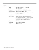
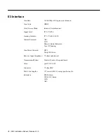
E3 Interface

Line Rate:

34.368 Mbps

±

 20 ppm, asynchronous.

Line Code:

HDB3.

Clock Source Mode:

Internal (Asynchronous).

Signal Level:

ITU-T G.703

Framing Formats:

ITU-T G.804, G.832,

Alarms Processed:

AIS.
LOS.
Remote Alarm Indication.
Loss Of Framing.

Line Errors Counted:

BPV.
Parity Bit Errors.

Receiver Input Impedance: 75 ohms unbalanced.

Transmission Modes:

Point-to-Point or Drop and Insert.

Jitter:

per ITU-T G.823.

Connector:

75 ohm BNC.

Max. Line Lengths:

137 meters (450 ft.) using specified cable.

Indicators:

RED Alarm.
YELLOW Alarm.
LOS.
AIS.

Содержание IGX 8

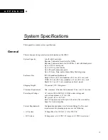
Страница 1: ...alone 24 5 ins 62 3 cm rack Width 19 9 ins 50 5 cm standalone 19 ins 48 3 cm rack Depth 26 5 ins 67 3 cm standalone and rack mount Shipping Weight 270 pounds 122 7 kilograms Clearance Requirement Min clearance 30 inches front nominal 30 ins rear 12 ins side Power Input Voltage AC system 100 to 240 VAC 90 264 under voltage and over voltage tolerance 47 to 63 Hz DC system 42 to 56 VDC Each AC supply...

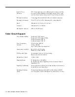
Страница 2: ...ce 24 channel T1 D4 format 24 channel T1 ESF using CVM8 30 channel framed CEPT E1 31 channel framed CEPT E1 Voice Compression Available 32 24 16 Kbps ADPCM 32 Kbps ADPCM Voice Activity Detection compression Compression Algorithm ITU T G 721 G 723 G 726 StrataCom 32 Kbps ADPCM PCM Encoding Types Accommodates µ Law or A Law encoding End to end conversion available Channel Gain Control 8 dB to 6 dB S...

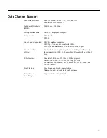
Страница 3: ...3 in each direction for DCE and DTE for each port Control Lead Sync w Data Control leads are sampled every 50 ms and changes will normally follow data within 100 to 1000 msec Fast EIA lead will be within 1 byte DS0A Interface Superrate 56 Kbps to 512 Kbps 8 DS0s per port Subrate One 2 4 4 8 9 6 19 2 or 56 Kbps per DS0 Per Bell TR TSY 000458 TR TSY 000280 TR TSY 000083 and TR TSY 000077 Data Clocki...

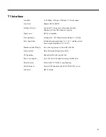
Страница 4: ...coding with bipolar violation sequences for zero suppression and control Data Compression Repetitive Pattern Suppression RPS 7 8 or 16 bit pattern matching Synchronization Modes External DSU only Looped OCU only Control Codes Recognized Idle Zero Suppression Out of Service Loopback Sequences Control Code Translation Translation of RTS to IDLE Alarm Code Translation Translation of the logical NOR o...

Страница 5: ...Bridged 1 KOhm Pulse Amplitude Individual pulse amplitude 2 4 V 3 6 V making a total base to peak amplitude of 6 V 6V Minimum Pulse Density Zero code suppression either LSB or MSB Frame Format D4 and Extended Superframe ESF VF Signalling Robbed bit D4 with A and B bits Max Line Lengths Up to 533 feet with equalizers using ABAM cable Jitter Transfer Meets AT T PUB 62411 specifications Jitter Tolera...

Страница 6: ...l G 703 Framed 30 or 31 channel CEPT multiframe per ITU T G 704 VF Signalling CAS or CCS Max Line Lengths E1 output complies with G 703 so cabling must not exceed 6dB 1000 feet at 1024 kHz applies to 75 Ohm coax or 120 Ohm twisted pair up to 350 meters or 1000 feet StrataCom supplies cable with a maximum attenuation of 7 dB 1000 ft so the maximum length of this cable is 850 feet 260 meters Jitter ...

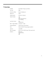
Страница 7: ...s Processed AIS LOS Remote Alarm Indication Loss Of Framing Line Errors Counted BPV Parity Bit Errors Receiver Input Impedance Terminated 75 ohms Transmission Modes Point to Point or Drop and Insert Jitter Meets ACCUNET T45 specification Pub 54014 Connector 75 ohm BNC Max Line Lengths 450 ft 137 m to DSX 3 using 75 Ohm coaxial cable Indicators RED Alarm YELLOW Alarm LOS AIS ...

Страница 8: ...Framing Formats ITU T G 804 G 832 Alarms Processed AIS LOS Remote Alarm Indication Loss Of Framing Line Errors Counted BPV Parity Bit Errors Receiver Input Impedance 75 ohms unbalanced Transmission Modes Point to Point or Drop and Insert Jitter per ITU T G 823 Connector 75 ohm BNC Max Line Lengths 137 meters 450 ft using specified cable Indicators RED Alarm YELLOW Alarm LOS AIS ...

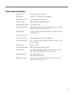
Страница 9: ...lable only with one of four ports card active No of Ports per Card 4 No of PVCs per Port 252 per FR card distributed in any combination Port Electrical Interface ITU T V 35 IGX 8 can act as a DCE or DTE for direction of control leads and timing Data Clocking Normal or looped Virtual Circuit Identifier Data Link Connection Identifier DLCI Control Protocol Local Management Interface with XON XOFF ty...

Страница 10: ...er AAL5 No of Ports per card 4 No of PVCs per card 255 VPI Addressing Range 0 255 VCI Addressing Range 0 65535 Traffic Queues CBR VBR and ABR Management Protocol Interim Layer Management Interface ILMI External Clock Sources The IGX switch synchronizes to the nearest highest stratm clock available Any T1 E1 T3 E3 OC3 STM 1 line trunk or optional external clock inputs can serve a clock source Inter...

Страница 11: ...ork alarms Remote Diagnostics Auto answer modem connects to one of two control ports on each IGX node for remote diagnostic access by StrataCom ISC or other authorized personnel Network Control Ports Two ports per node one RS 232C interface and one Ethernet LAN port Alarm Notification Status of all trunks and nodes in network distributed to and stored by each individual node Reported to StrataView...

Страница 12: ... 12 IGX 8 Installation Manual Release 8 2 0 ...

Отзывы: