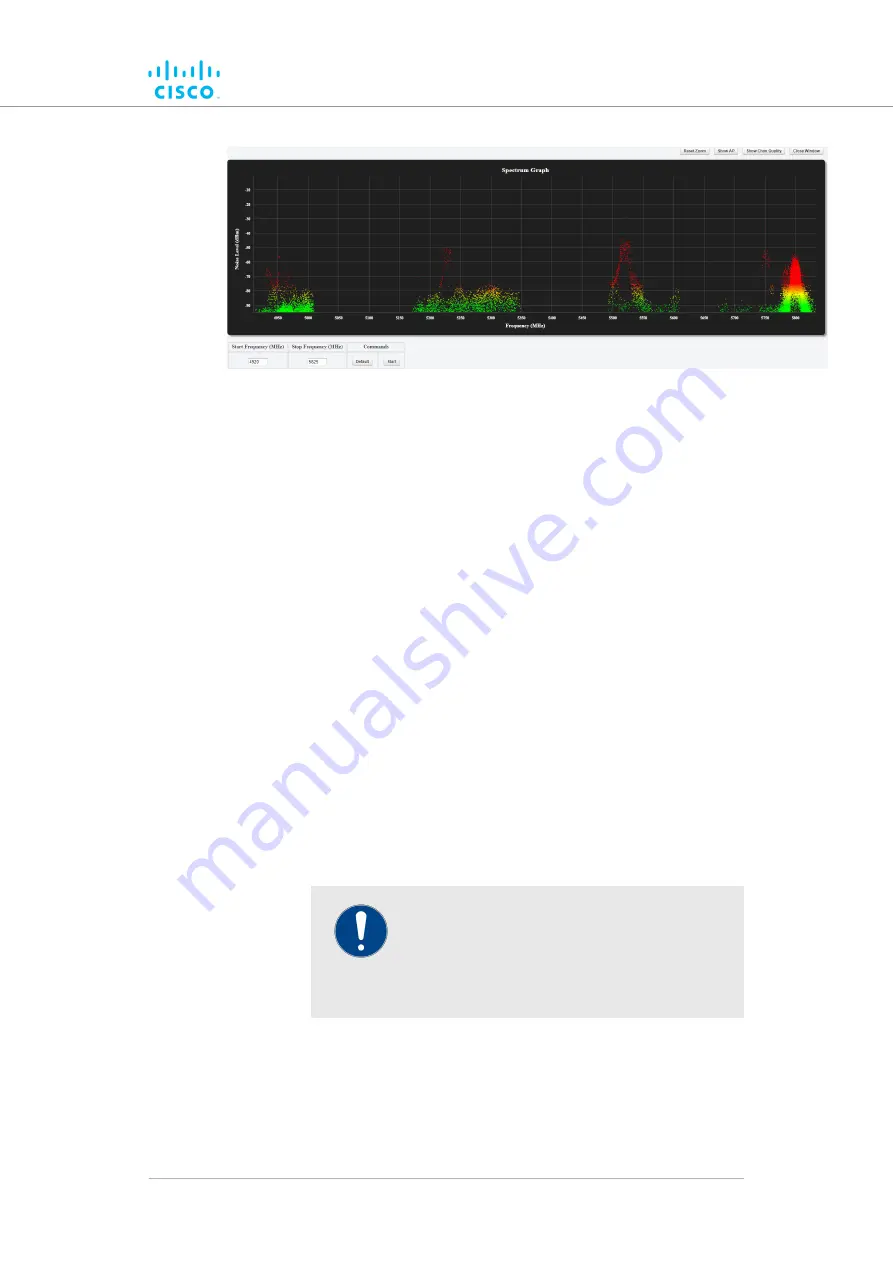
Figure 29. Spectrum Graph window (typical display)
• The Spectrum Graph readout will be empty.
2.
Choose a range for the frequency band that must be scanned for
interference or excessive radio noise by doing either of the
following:
• Set the start and stop frequency selection to the system
defaults (4 950 MHz to 5 825 MHz) by clicking
the
Default
button.
• Enter custom start frequency and stop frequency values for
the frequency band that must be scanned for interference,
in the
Start Frequency (MHz)
and
Stop Frequency (MHz)
fields.
In the
3.
Commands
table, click the
Start
button.
• When the frequency scan is complete, the Spectrum Graph
window will show the scan result.
• Signal quality for each channel is shown as a function of
signal noise quantity (in decibel-milliwatts) at each
frequency. The higher the value shown on the graph, the
poorer the signal quality. A green display indicates high
signal quality. Yellow indicates falling quality. If the signal
display is red, there is excessive signal noise.
IMPORTANT
If you are scanning a network with overlapping
communication channels, the number of
detected
Cisco units may be larger thanthe
actual
number of deployed units.
4.
To view a specific part of the graph, roll the mouse wheel forward
to zoom into the window, then click-and-drag the window left or
right.
5.
To reset the window to default size, click the
Reset Zoom
button
on the upper right-hand corner of the
Spectrum Graph
window.
Device configuration using the configurator interface
© 2021 Cisco and/or its affiliates. All rights reserved.
Page 71 of 175


