


• The
Appearance / Background
dialog will be shown.
2.
If the
Background
settings are shown, click the
Appearance
heading.
3.
Click the
KPI values on routes
switch from
Off
to
On
.
4.
Click the check-boxes for each KPI you want to see for all
wireless links. Available options are:
• L.E.R. (Current link error rate, shown as a percentage)
• P.E.R. (Current packet error rate, shown as a percentage)
• RSSI (Current received signal strength, shown in dBm)
• Link Utilization (shown as a percentage)
5.
To save your changes, click the
Save changes
button.
Alternatively, click the
Discard
button to leave the dialog without
saving any changes.
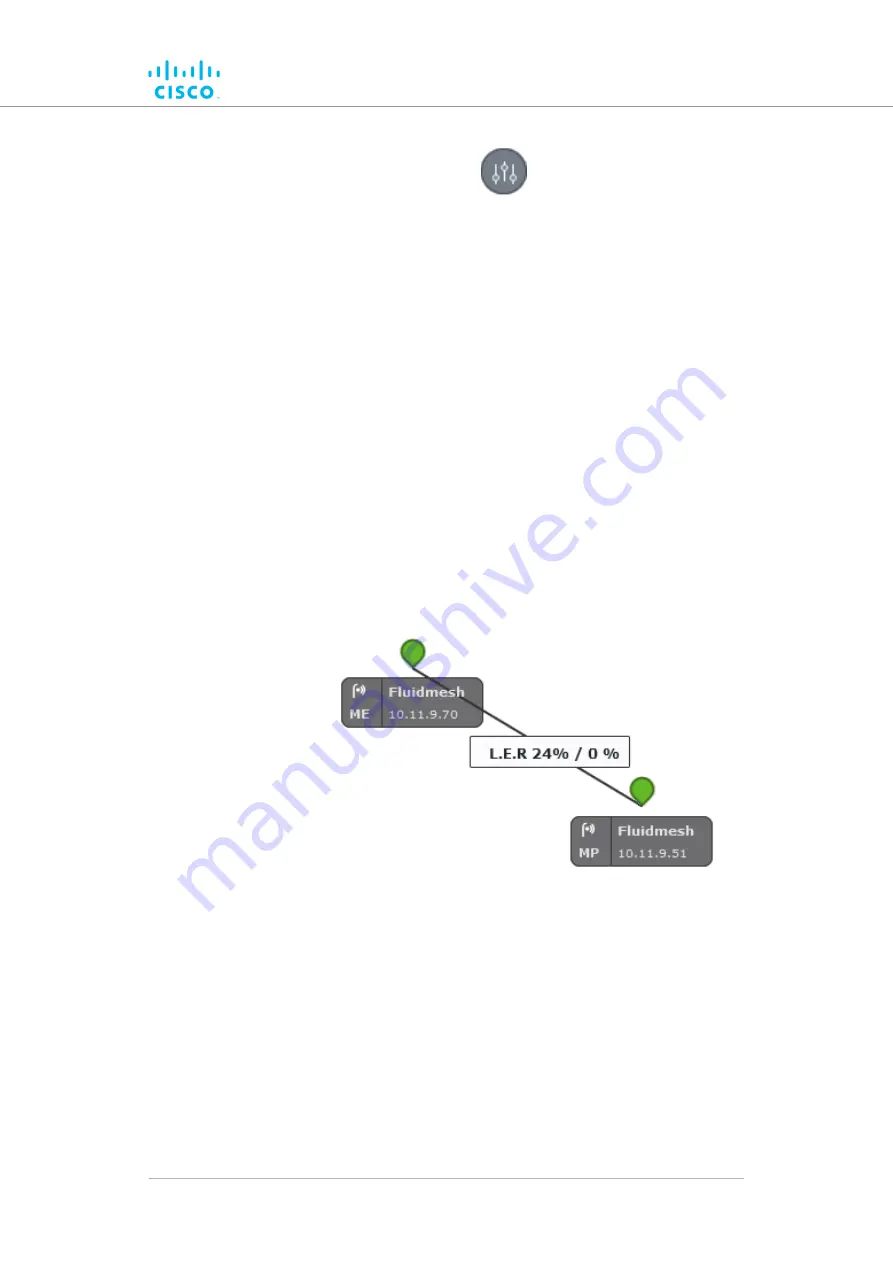
• An information ribbon containing the chosen key
performance indicators will be shown next to all wireless
link lines (a typical example is shown below).
Adding an aerial map to the FM-QUADRO view
You can add an aerial image to the FM-QUADRO view. This allows you to
superimpose the network map over a map of the actual terrain on which
the network has been installed, making it easier to visualize component
placement, line-of-sight between antennas, and other factors.
To add an aerial terrain map to the FM-QUADRO view, do the following
steps:
Device configuration using the configurator interface
© 2021 Cisco and/or its affiliates. All rights reserved.
Page 64 of 132


