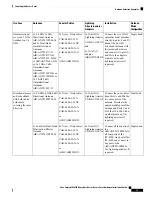
Antenna
Mode
Configuration
Installation
Lightning
Arrestors and/or
Adapters
Coaxial Cables
Antennas
Use Case
Single band
Connect the 2.4 GHz
panel to ports A and B,
connect the 5 GHz panel
to ports C and D. Use
lightning arrestors if
required.
4x N(m)-N(f)
Lightning Arrestor
CGR-LA-NM-NF
and 4x N(f)-N(f)
adapter
AIR-ACC370-NF-NF
4x N(m) – N(m) cables:
CAB-L400-5-N-N
CAB-L400-5-N-NS
CAB-L400-20-N-N
CAB-L600-30-N-N
or
AIR-CAB025HZ-N
1x 2.4 GHz 13 dBi
Directional Antenna
AIR-ANT2413P2M-N=
and 1x 5 GHz 13 dBi
Directional Antenna
AIR-ANT5114P2M-N=
Directional
coverage and/or
backhaul with
both radios; each
radio covering a
different direction
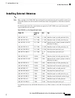
Non-Cisco Antennas
Cisco does not support any third-party antennas. RF connectivity and compliance of third party antennas is
the user’s responsibility. Cisco does not recommend any third-party antennas, and Cisco Technical Assistance
Center will not be able to provide any support for third-party antennas. Cisco’s FCC Part 15 compliance is
only guaranteed with Cisco antennas or antennas that are of the same design and gain as Cisco antennas.
Grounding the Access Point
The access point must be grounded before connecting power.
In all outdoor installations you must follow these instructions to properly ground the case:
Procedure
Step 1
If using insulated 6-AWG copper ground wire, strip the insulation as required for the grounding lug.
Step 2
Use the appropriate crimping tool to crimp the bare 6-AWG copper ground wire to the supplied grounding
lug.
The grounding lug and hardware used must comply with local and national electrical codes.
Note
Step 3
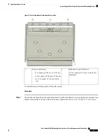
Open the anti-corrosion sealant (supplied), and apply a liberal amount over the metal surface, called the Ground
Pad, where the ground strap screw holes are located (see the following figure).
Cisco Catalyst IW6300 Heavy Duty Series Access Point Hardware Installation Guide
38
Installing the Access Point
Non-Cisco Antennas

