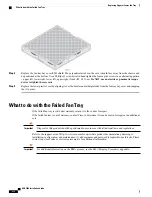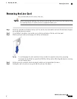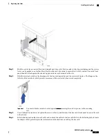
Step 4
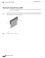
Replace the fan tray bay cover/EMI shield. The perpendicular tabs on the cover should face away from the chassis and
be positioned at the bottom. Use a Phillips #1 screwdriver to hand tighten the four captive screws in an alternating pattern
–
upper left, lower right, lower left, upper right (5 inch-lbf, 0.5 N-m).
Do NOT use an electric or pneumatic torque
driver to tighten these screws.
Step 5
Replace the lower plastic bezel by aligning it over the bezel mounts that protrude from the fan tray bay cover and snapping
the it in place.
What to do with the Failed Fan Tray
If the failed fan tray is still under warranty, return it to the vendor for repair.
If the failed fan tray is out of warranty, contact Cisco to determine if it can be sent in for repair at an additional
cost.
Disposal of this product should be performed in accordance with all national laws and regulations.
Important
Refer to the support area of http://www.cisco.com for up-to-date product documentation pertaining to
installation, configuration, and maintenance. A valid username and password is required to use this site. Please
contact your local sales or service representative for additional information.
For additional information on the RMA process, see the
RMA Shipping Procedures
appendix.
Important
ASR 5000 Installation Guide
212
Replacing Upper or Lower Fan Tray
What to do with the Failed Fan Tray
Содержание ASR 5000
Страница 16: ...ASR 5000 Installation Guide xvi About this Guide Contacting Customer Support ...
Страница 64: ...ASR 5000 Installation Guide 48 Installation Procedure Overview Laser Notice ...
Страница 100: ...ASR 5000 Installation Guide 84 Line Card Installation Installing the XGLC ...
Страница 118: ...ASR 5000 Installation Guide 102 Cabling the Switch Processor Input Output Line Card Central Office Alarm Wiring Example ...
Страница 122: ...ASR 5000 Installation Guide 106 Cabling the Fast Ethernet 10 100 Line Card FLC2 Interfaces ...
Страница 136: ...ASR 5000 Installation Guide 120 Cabling the Optical ATM Line Cards Cabling the Optical SFP Interface ...
Страница 140: ...ASR 5000 Installation Guide 124 Cabling the Channelized Line Cards Cabling the Optical SFP Interface ...
Страница 144: ...Figure 49 PFU Wiring Diagram ASR 5000 Installation Guide 128 Cabling the Power Filter Units Power Cable Requirements ...
Страница 148: ...ASR 5000 Installation Guide 132 Cabling the Power Filter Units Connecting the PFU to the Power Source ...
Страница 206: ...ASR 5000 Installation Guide 190 Removing and Installing SMC PC Cards Removing PC Cards ...
Страница 212: ...ASR 5000 Installation Guide 196 Replacing the Chassis Air Filter Installing the Air Filter ...
Страница 220: ...ASR 5000 Installation Guide 204 Replacing a Power Filter Unit What to do with the Failed PFU ...
Страница 266: ...ASR 5000 Installation Guide 250 Safety Electrical and EMC Certifications Korean EMC ...
Страница 270: ...ASR 5000 Installation Guide 254 Environmental Specifications Chassis Air Flow ...
Страница 280: ...ASR 5000 Installation Guide 264 Preparing a Full Height Line Card Slot Remove the Half Height Card Guide ...
Страница 294: ...ASR 5000 Installation Guide 278 Spare Component Recommendations Spare Component Recommendations ...

