Value
Characteristic
SPIO:
15W
FLC2:
13.5W
GLC2:
10.5W
RCC:
20W
QGLC:
15W
XGLC:
25W
OLC2:
23W
CLC2:
23W
Line Card (rear-installed) Maximum
Power Load
SMC:
130W
PSC:
250W
PSC2:
325W
PSC3:
330W
PPC:
275W
Application Card (front-installed)
Maximum Power Load
PFU:
165 Amps
Power Feed
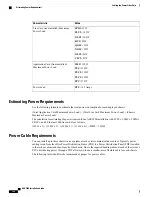
Estimating Power Requirements
Use the following formula to estimate the total power consumption for each deployed chassis:
(Total Application Card Maximum Power Load) + (Total Line Card Maximum Power Load) + (Chassis
Maximum Power Load)
The calculation for estimating the power required for an ASR 5000 installation with 3 PSCs, 2 SMCs, 2 SPIOs,
2 RCCs, and 4 Ethernet 1000 line cards is as follows:
(250W x 3) + (130W x 2) + ((20W x 2) + (13.5W x 4)) + 800W = 1934W
Power Cable Requirements
You can install up to three chassis in an equipment rack or telecommunications cabinet. Typically power
cabling is run from the office Power Distribution Frame (PDF) to a Power Distribution Panel (PDP) installed
in the rack or cabinet and then to each of the chassis. Due to the required bending radius at each of the system's
PFUs, distributing power through a PDP allows you to use a smaller, more flexible cable for each chassis.
The following table identifies the recommended gauges for power cables.
ASR 5000 Installation Guide
126
Cabling the Power Filter Units
Estimating Power Requirements
Содержание ASR 5000
Страница 16: ...ASR 5000 Installation Guide xvi About this Guide Contacting Customer Support ...
Страница 64: ...ASR 5000 Installation Guide 48 Installation Procedure Overview Laser Notice ...
Страница 100: ...ASR 5000 Installation Guide 84 Line Card Installation Installing the XGLC ...
Страница 118: ...ASR 5000 Installation Guide 102 Cabling the Switch Processor Input Output Line Card Central Office Alarm Wiring Example ...
Страница 122: ...ASR 5000 Installation Guide 106 Cabling the Fast Ethernet 10 100 Line Card FLC2 Interfaces ...
Страница 136: ...ASR 5000 Installation Guide 120 Cabling the Optical ATM Line Cards Cabling the Optical SFP Interface ...
Страница 140: ...ASR 5000 Installation Guide 124 Cabling the Channelized Line Cards Cabling the Optical SFP Interface ...
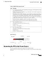
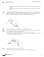
Страница 144: ...Figure 49 PFU Wiring Diagram ASR 5000 Installation Guide 128 Cabling the Power Filter Units Power Cable Requirements ...
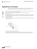
Страница 148: ...ASR 5000 Installation Guide 132 Cabling the Power Filter Units Connecting the PFU to the Power Source ...
Страница 206: ...ASR 5000 Installation Guide 190 Removing and Installing SMC PC Cards Removing PC Cards ...
Страница 212: ...ASR 5000 Installation Guide 196 Replacing the Chassis Air Filter Installing the Air Filter ...
Страница 220: ...ASR 5000 Installation Guide 204 Replacing a Power Filter Unit What to do with the Failed PFU ...
Страница 266: ...ASR 5000 Installation Guide 250 Safety Electrical and EMC Certifications Korean EMC ...
Страница 270: ...ASR 5000 Installation Guide 254 Environmental Specifications Chassis Air Flow ...
Страница 280: ...ASR 5000 Installation Guide 264 Preparing a Full Height Line Card Slot Remove the Half Height Card Guide ...
Страница 294: ...ASR 5000 Installation Guide 278 Spare Component Recommendations Spare Component Recommendations ...

