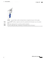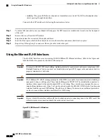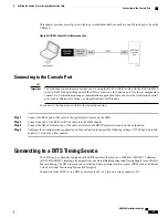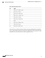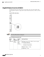
This adapter provides a serial port on a laptop or workstation that does not have one. It draws power from the
USB port.
Figure 35: USB to Console Port Interconnection
Connecting to the Console Port
The following instructions assume that you are using the RJ-45-to-RJ-45 cable with the RJ-45-to-DB-9
serial (EIA-232) adapter shipped with the SPIO to connect to the Console port. Use these components to
connect to a workstation running a communications application that can access the workstation's serial
port, such as Minicom for Linux
®
or HyperTerminal
®
for Windows.
Important
To connect to the Console port, follow the instructions below.
Step 1
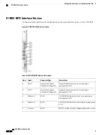
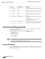
Connect the RJ-45 end of the cable to the port labeled Console on the SPIO.
Step 2
Connect one end of the RJ-45-to-RJ-45 cable into the DB-9 adapter.
Step 3
Connect the DB-9S (female) end of the cable assembly to the DB-9P (male) serial port on the workstation.
Step 4
Configure the communications application on the workstation to support the following settings: 115200 bps, 8 data bits,
no parity, 1 stop bit, no flow control.
Connecting to a BITS Timing Source
The SPIO can be optionally equipped with a BITS interface that derives a 1544 kHz (SONET T1 framing)
or 2048 kHz (SDH E1 framing) clock signal from an external Building Integrated Timing Supply to synchronize
line card timing. The BITS source derives its timing from a primary reference source (PRS), such as a Stratum
1 clock or Global Positioning System (GPS) signal.
Connection to the BITS is via a BNC coaxial cable (E1) or 3-pin wire-wrap connector (T1).
ASR 5000 Installation Guide
95
Cabling the Switch Processor Input/Output Line Card
Connecting to the Console Port
Содержание ASR 5000
Страница 16: ...ASR 5000 Installation Guide xvi About this Guide Contacting Customer Support ...
Страница 64: ...ASR 5000 Installation Guide 48 Installation Procedure Overview Laser Notice ...
Страница 100: ...ASR 5000 Installation Guide 84 Line Card Installation Installing the XGLC ...
Страница 118: ...ASR 5000 Installation Guide 102 Cabling the Switch Processor Input Output Line Card Central Office Alarm Wiring Example ...
Страница 122: ...ASR 5000 Installation Guide 106 Cabling the Fast Ethernet 10 100 Line Card FLC2 Interfaces ...
Страница 136: ...ASR 5000 Installation Guide 120 Cabling the Optical ATM Line Cards Cabling the Optical SFP Interface ...
Страница 140: ...ASR 5000 Installation Guide 124 Cabling the Channelized Line Cards Cabling the Optical SFP Interface ...
Страница 144: ...Figure 49 PFU Wiring Diagram ASR 5000 Installation Guide 128 Cabling the Power Filter Units Power Cable Requirements ...
Страница 148: ...ASR 5000 Installation Guide 132 Cabling the Power Filter Units Connecting the PFU to the Power Source ...
Страница 206: ...ASR 5000 Installation Guide 190 Removing and Installing SMC PC Cards Removing PC Cards ...
Страница 212: ...ASR 5000 Installation Guide 196 Replacing the Chassis Air Filter Installing the Air Filter ...
Страница 220: ...ASR 5000 Installation Guide 204 Replacing a Power Filter Unit What to do with the Failed PFU ...
Страница 266: ...ASR 5000 Installation Guide 250 Safety Electrical and EMC Certifications Korean EMC ...
Страница 270: ...ASR 5000 Installation Guide 254 Environmental Specifications Chassis Air Flow ...
Страница 280: ...ASR 5000 Installation Guide 264 Preparing a Full Height Line Card Slot Remove the Half Height Card Guide ...
Страница 294: ...ASR 5000 Installation Guide 278 Spare Component Recommendations Spare Component Recommendations ...


