


E-4
Cisco Wireless LAN Controller Configuration Guide
OL-17037-01
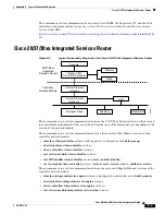
Appendix E Logical Connectivity Diagrams
Catalyst 3750G Integrated Wireless LAN Controller Switch
•
test HW-module
integrated-service-engine
slot/unit
reset
{
enable
|
disable
}
•
service-module integrated-service engine
slot
/
port
{
reload
|
reset
|
session
[
clear
] |
shutdown
|
status
}
Note
Refer to the
Cisco Wireless LAN Controller Network Module Feature Guide
for more information. You
can find this document at this URL:
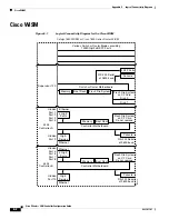
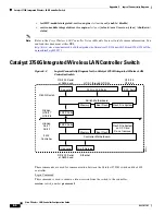
Catalyst 3750G Integrated Wireless LAN Controller Switch
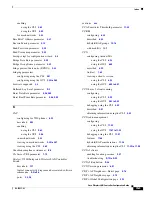
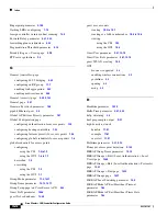
Figure E-3
Logical Connectivity Diagram for the Catalyst 3750G Integrated Wireless LAN
Controller Switch
These commands are used for communication between the Catalyst 3750G switch and the 4402
controller.
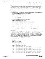
Login Command
This command is used to initiate a telnet session from the switch to the controller:
session
switch_number
processor 1
3750G Switch
4402
Controller
Hidden
G1/0/27
G1/0/28
155911
24 Gig PoE Ports
Switch Motherboard
Controller Motherboard
Console
Console
Gig E Service
RS-232 Serial
at 9600 baud
Ethernet
2 SFP Ports
G1/0/1 through G1/0/24
RS-232 Serial
at 9600 baud
G1/0/25
G1/0/26
2 SFP Ports
Hidden
Port 1
Port 2
2 SFP Ports
Memory
Boot Flash
Flash File System
Memory
Boot Flash
Flash File System
on CF Card
Do not remove


