12
RECmax-CVM
Instruction Manual
Warranty
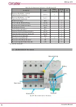
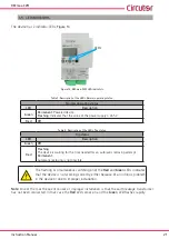
, Once the central part of the seal has been removed, the side section of the seal
must remain attached�
DO NOT REMOVE
this part, it ensures that the insulated busbar at the
top of the circuit breaker has not been removed or tampered with�
The warranty of the device will be void
if the safety seal has been tam-
pered with or removed�
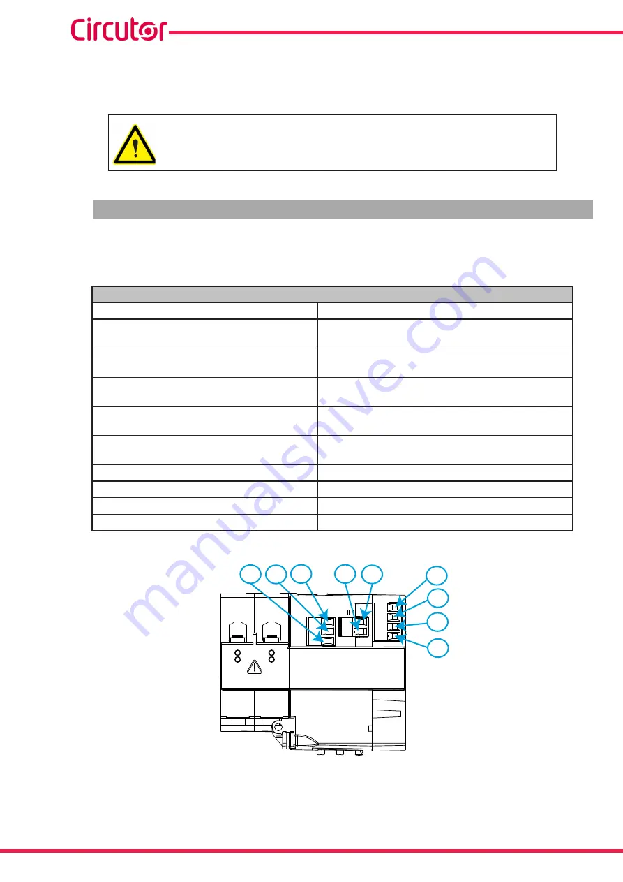
3�3�- TERMINALS OF THE DEVICE
The
RECmax-CVM
terminals are distributed between the upper and lower face of the device�
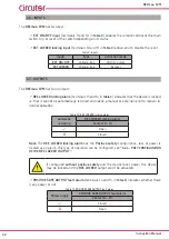
Table 3:List of RECmax-CVM terminals�
Terminals of the RECmax-CVM device
1:
Earth leakage current input IΔ
13:
REC LOCKED
, REC LOCKED Locking Alarm Output (NO)
2:
Earth leakage current input IΔ
14:
POSITIVE SAFE OUTPUT and REC LOCKED common
output
3: S,
RS-485 Communications
15:
POSITIVE SAFE OUTPUT
, POSITIVE SAFE OUTPUT
Alarm Output (NO)
4: B-,
RS-485 Communications
16:
BREAKER ON/OFF
, Indicates the status of the main
switch (Common)
(1)
5: A+,
RS-485 Communications
17:
BREAKER ON/OFF
,Indicates the status of the main
switch (NC)
(1)
7:
S0-
, Digital Output
18:
BREAKER ON/OFF
, Indicates the status of the main
switch (NO)
(1)
8:
S0+
, Digital Output
19: 1S1
, Current input L1
9:
EXT� ON/OFF
, EXT ON/OFF Control Input (NO)
20:
2S1
, Current input L2 (
RECmax-CVM
4-pole model)
10:
EXT LOCKED and EXT ON/OFF common output
21:
3S1
, L3 current input (
RECmax-CVM
4-pole model)
11:
EXT LOCKED
, EXT LOCKED locking input (NO)
22:
C
, Common connector for current measurement
(1)
�
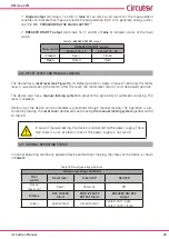
1
2
16 17 18
19
20
21
22
Figure 4:RECmax-CVM terminals, upper face�
Содержание RECmax-CVM 2-pole
Страница 2: ...2 RECmax CVM Instruction Manual...
Страница 13: ...13 Instruction Manual RECmax CVM 9 10 11 13 14 15 3 4 5 7 8 Figure 5 RECmax CVM terminals lower face...
Страница 65: ...65 Instruction Manual RECmax CVM 11 CE CERTIFICATE...
Страница 66: ...66 RECmax CVM Instruction Manual...
Страница 67: ...67 Instruction Manual RECmax CVM...


