background image

4

© 2011 Cinch Connectors V2 10-2011

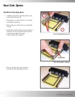
Heat Sink Option

Mosfet TO220

Press fit spring plates into board

Slots (2) for Spring Plate press fit

R

L

•  Refer to Cinch header prints for specific 

board layout and spring plate selection.

Install heat sink spring plates

•  Install the spring plates after the printed circuit 

board has been processed. 

•  Spring plates are marked “R” and “L” and must 

be installed as indicated. 

•  When using a one (1) heat sink, use spring plate 

“R” only. 

•  Spring plates and thermally conductive adhesive 

paste are necessary to guarantee proper heat 

conduction through the heat sinks; 

Cinch recommends Loctite 383.

Содержание ModICE LE

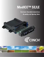
Страница 1: ...ModICE SE LE Enclosure Assembly Instructions Assembly and Opening Tools ...

Страница 2: ...er applications Available options Header with ferrite filter Enclosure with 1 or 2 heat sinks Enclosure with breather membrane NOTE The heat sink feature requires additional steps in the assembly of the printed circuit board Header Enclosure Ferrite filter optional Heat Sink optional Spring Plate for Heat Sink optional For technical or ordering information on Transportation products contact Cinch ...

Страница 3: ...ting Ferrites must be immobilized by using conformal coating or a bead of epoxy Secure Header onto the board Headers must be secured to the board with 2 screws Use two 4 self tapping screws Torque 2 3 in lbs 0 23 0 34 Nm Refer to the Cinch Header drawings for board layout keep out areas and component height restrictions ...

Страница 4: ...ng plate selection Install heat sink spring plates Install the spring plates after the printed circuit board has been processed Spring plates are marked R and L and must be installed as indicated When using a one 1 heat sink use spring plate R only Spring plates and thermally conductive adhesive paste are necessary to guarantee proper heat conduction through the heat sinks Cinch recommends Loctite...

Страница 5: ... Enclosure Holder Header Alignment Blocks Down SE position shown Enclosure Holder in SE position Header Alignment Blocks Up LE position shown Enclosure Holder in LE Position Tool p n 5991111650 The assembly tool is common to the ModICE SE and LE Enclosures Simple settings to convert from the SE to the LE size ...

Страница 6: ...1 ModICE Assembly Tool SE SE Enclosure Holder Settings Header Holder Settings Move Enclosure Holder to the back for the LE position For LE setting lift up the two alignment blocks LE LE Tool Settings for Small SE and Large LE Enclosure ...

Страница 7: ...e in the up position for LE headers see previous page Slide Push the Header PCB into the holder snap fit retention by spring plunges Load Enclosure into the holder Check SE LE position on the previous page 1 2 1 Push for snap fit Alignment Block Spring plunge 1 2 ModICE Assembly NOTE Check gasket for proper alignment before assembly Gasket should not be twisted or dislodged from corners during han...

Страница 8: ...1 Close the assembly tool Push lever to assemble Header PCB into the Enclosure Push all the way down to close the enclosure audible snaps Open the assembly tool Hold the enclosure down while releasing the lever ModICE Assembly 3 4 3 4 ...

Страница 9: ...on is required to verify proper engagement of all the locking tabs Manual engagement of the minitabs may be necessary to complete the assembly Press the Enclosure over the Header so that all minitabs are engaged Mini locking tabs x6 SE Enclosure x10 LE Enclosure Tab Engaged Tab Not Engaged ModICE Assembly 5 5 ...

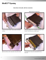
Страница 10: ...s are required to open the enclosures Any attempt to open an enclosure without the recommended tools may result in damaged parts that will affect the mechanical characteristics and the sealing of the enclosure ModICE Opening Tool Tool p n 5991111611 ModICE SE Tool p n 5991111612 ModICE LE ...

Страница 11: ...aders with two connectors Position the tool so that the screws capture both Header bushings Both side latches must be unlocked to release the header Alternately tighten each screw evenly until release of the Header from the Enclosure audible snaps Pull straight out to remove the Header PCB from the Enclosure ...

Страница 12: ...or headers with one connector Position the tool so that the screw captures the Header bushing On a flat surface press on opposite side of the tool to release latch B Header will pop open Tighten screw all the way down to release side latch A audible snap Pull straight out to remove the Header PCB from the Enclosure ...

Страница 13: ...ors V2 10 2011 ModICE Opening Tool Untighten screws to release the tool from the header In the case of a customized header customer may be required to modify the opening tool to allow it to work for the specific application ...

Страница 14: ...n mounting application Fastening pattern 1 2 3 4 Torque 10 12 in lbs 1 13 1 36 Nm Refer to Cinch SHS Harness Connector drawings and instructions for information on the mating connectors Connector Mating Torque 15 20 in lbs 1 70 2 26 Nm 1 3 4 2 For technical or ordering information on Transportation products contact Cinch at 630 705 6000 or visit our website at www cinch com ...

Отзывы: