background image

11 - TECHNICAL CHARACTERISTICS

11.1 - Basic components

11.1.1 - Control

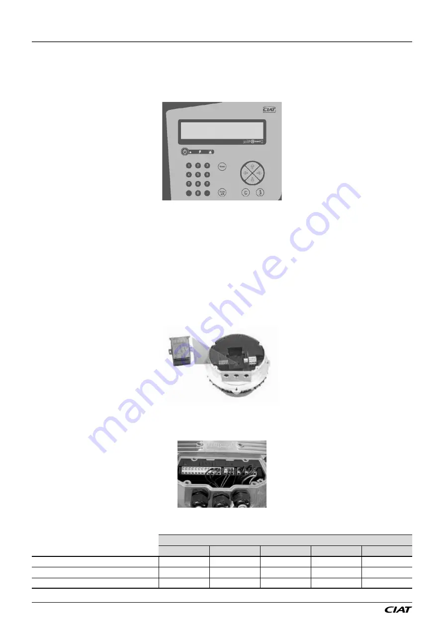
The vertical units are equipped with a CIAT µAIR CONNECT2 automatic control unit.

CIAT µ Air Connect 2

The heart of the vertical unit, this manages the unit and ensures it functions correctly. It is built into the display.
It can be connected to control systems so that the vertical unit can be controlled remotely, or to allow for master/slave control with 

several vertical units.

For adjustment and configuration, refer to the corresponding manual (N09.41).

11.1.2 - 

Fan motor assembly (FMA)

EC motor (electronic communication) with "plug fan" type direct drive.
Thanks to their technology, these fans have low energy consumption.

Type of FMA control:


-

With the µRC2.1 control

• On CW40 to 100 vertical units: MODBUS control as the FMAs are equipped with a MODBUS card that sends the following 

information to the controller: rotation speed, current used and power input.

• On CW115 vertical units: progressive 0-10 V control.


-

No control 

• Progressive 0-10 V control via a manual voltage potentiometer located inside the electrics box (graduated from 0 to 100 %)

CHILLED WATER

CW 40

CW 53

CW 78

CW 100

CW115

Quantity

1

1

2

2

3

Max. power (kW)

3,4

3,4

6,8

6,8

9,3

Max. current (A)

5,4

5,4

10,8

10,8

14,7

MAGISTER

®

 EN-14 


Содержание MAGISTER Series

Страница 1: ...Instruction manual MAGISTER 06 2021 EN7558843 03 ...

Страница 2: ...TYPE 6 8 LOCATION INSTALLATION 7 9 LOCATION AND MARKING OF COMPONENTS 8 10 CONNECTIONS 10 10 1 Hydraulic connection 10 10 2 Electrical connection 11 11 TECHNICAL CHARACTERISTICS 14 11 1 Basic components 14 11 2 Optional components 17 12 COMMISSIONING 26 13 MAINTENANCE 27 13 1 Filters 28 13 2 Cooling coil 29 13 3 Humidifier 30 13 4 Fans 31 13 5 Electrics box 34 14 SERVICE INTERVALS 35 15 OPERATING ...

Страница 3: ...e locations DATA CENTRES computer rooms metrology laboratories etc The description of the unit is indicated using the following format MAGISTER X X X B C D E Example of description MAGISTER CW40 UNDER1 B Range C Unit type CW chilled water D Cooling capacity E Assembly type direction of air flow UNDER1 Return air above supply air underneath OVER3 Return air in front supply air above OVER5 Return ai...

Страница 4: ...r This number must be quoted in all correspondence B Product reference C Product description D Year of manufacture E Serial no to be quoted in all correspondence F Type of fluid used in the exchanger and operating pressure G Cooling capacity water temperature used H Heating capacity water temperature used if heating coil option usage type 2 stages or TRIAC if electric heater option I Information o...

Страница 5: ...and standards 4 WARRANTY See the general terms and conditions of sale 5 STORAGE OF EQUIPMENT The cabinet must be stored in a dry sealed area away from moisture and frost The temperature in this area must not exceed 50 C 6 HANDLING The unit must be handled either with a pallet truck or using a spreader beam and slings This operation must be carried out by qualified personnel Refer to the informatio...

Страница 6: ... tubing Ø max 40 mm with a sufficient lifting capacity see weight table Use fabric slings 6 1 Weights and dimensions SIZE Dimensions H x W x D Weight kg CW 40 1990 x 1190 x 890 350 CW 53 1990 x 1520 x 890 385 CW 78 1990 x 2070 x 890 545 CW 100 1990 x 2620 x 890 635 CW115 1990 x 3000 x 890 730 7 SUPPLY AIR TYPE 3 supply air types Fitting UNDER Return air above supply a i r u n d e r n e a t h Fitti...

Страница 7: ...of the following bases Support base cased base with grids cased base with damper See the technical characteristics for these options in paragraph 12 2 It should be placed on a floor that is as level as possible Each base comes with feet which allow the height to be adjusted in the event of a raised floor and the base to be levelled before placing the unit on top Before placing the vertical unit on...

Страница 8: ... coil Electrics Box Cooling coil Electric heater option Additional cabinet Drain pump option Condensate drain pump option CW40 to CW100 Over Assembly FMA Electrics Box Control valve Heating coil Cooling coil Heating coil option Control valve cooling coil Humidifier option Filters Cooling coil Electric heater option Condensate drain pump option Additional cabinet Drain pump option MAGISTER EN 8 ...

Страница 9: ...CW115 Under Assembly Electric heater option Access hatches Filters Electrics Box Cooling coil Control valve cooling coil Humidifier Option FMA 9 LOCATION AND MARKING OF COMPONENTS EN 9 MAGISTER ...

Страница 10: ...CW 100 Heating coil Inlet G 3 4 M G 3 4 M G 3 4 M G 3 4 M Outlet G 3 4 M G 3 4 M G 3 4 M G 3 4 M Always use two spanners when connecting or tightening the hydraulic couplings to avoid twisting the pipes and applying stress on the welds To avoid the risk of condensation the hydraulic pipes and elements must be carefully insulated Before insulating check the tightness of the couplings Warning the op...

Страница 11: ...l power supply conform with the indications on the name plate Please ensure the unit is connected to earth and that the power supply is always able to supply the necessary power Electrical specifications Three phase 400 V power supply Earth 50 Hz Table of currents CW 40 CW 53 CW 78 CW 100 CW115 Fan motor assembly Voltage V 400 Power kW 3 4 6 8 9 3 Current A 5 4 10 8 14 7 Control circuit transforme...

Страница 12: ... slave control as well as room sensors go through the top of the cabinet and the top section of the box through the grommets shown in the box views In all cases avoid following the power supply cables to avoid interference to the signals sent Recommendations concerning the cables and routing in the box For the communication cables BUS RS485 cable Multiconductor shielded jacketed cable shielding wi...

Страница 13: ... BUS RS 485 cable Raceways Raceways Route for BACNET BUS cable Gateway BACNET All the cable routings in the unit must be sealed tight The CW115 model is supplied with covers which must be fitted on the side and front section of the casing 10 CONNECTIONS EN 13 MAGISTER ...

Страница 14: ...1 2 Fan motor assembly FMA EC motor electronic communication with plug fan type direct drive Thanks to their technology these fans have low energy consumption Type of FMA control With the µRC2 1 control On CW40 to 100 vertical units MODBUS control as the FMAs are equipped with a MODBUS card that sends the following information to the controller rotation speed current used and power input On CW115 ...

Страница 15: ...connections to avoid damaging the manifolds The coil is regulated by a two way or three way valve equipped with a 0 10V servomotor mounted and connected Coil specifications CHILLED WATER CW 40 CW 53 CW 78 CW 100 CW115 Coil 4 row coil Number of coils 1 1 1 1 1 Capacity l 11 8 15 8 21 27 4 50 8 Coil 6 row coil Number of coils 1 Capacity l 73 8 Units CW 40 CW 53 CW 78 CW 100 CW115 Air flow m3 h 10 00...

Страница 16: ...94 132 132 124 124 Water flow m3 h 9 6 10 16 23 21 Pressure drop mWC Coil valve 10 10 10 10 10 Conditions return air 32 C 35 RH Water temperature 12 17 C Maximum operating pressure dependent on air flow rate Take off approximately 20 Pa if there is a hot water coil on the MAGISTER The operation point can be adjusted directly via the controller All air flow operating pressure combinations are there...

Страница 17: ... components 11 2 1 Heating coil Moderately tighten the coil supply connections to avoid damaging the manifolds The coil is adjusted by a two way or four way valve equipped with a 0 10V servomotor mounted and connected Coil specifications HOT WATER CW 40 CW 53 CW 78 CW 100 Coil 1 row Number of coils 1 1 1 1 Capacity l 3 82 4 92 6 29 6 29 HEATING COIL CW 40 CW 53 CW 78 CW 100 CW115 Nominal Maximum N...

Страница 18: ...s and an electrical current passes between them heating the water to boiling point The water acts as an electrical resistor ensuring continuity between the electrodes with a minimum of dissolved salts The water must have a conductivity of between 350 µS cm and 125 µS cm CW 40 to CW115 Make model KUET 2D Control voltage 24 V Absorbed power in control circuit Without 9 V A valve with 35 V A valve Hi...

Страница 19: ...The pressure drops defined in this table are calculated using 10 mm diameter flexible piping Discharge height Total pipe length 5 m l h 10 m l h 20 m l h 30 m l h 1 m 460 380 280 200 2 m 390 320 240 180 3 m 300 250 190 150 4 m 200 180 130 100 5 m 90 80 60 50 Connect a Ø 10 int 3 8 flexible tube not supplied by CIAT to the pump discharge For OVER models 3 and 5 if using a spreader beam and slings t...

Страница 20: ...ouble deflection grids Grommet for power supply cable connection Plate for hydraulic or refrigerant connection Can be used for both intake and supply air The height can be adjusted from 450 mm to a maximum of 860 mm Adjustment screws are provided for adjustment on site Do not forget to stick the adhesive seal provided to the aluminium frame of the base to ensure its tightness Made up of double def...

Страница 21: ... servomotor access as well as a grommet for the power supply cable 11 2 6 Plenums Supply air intake plenum H 450 mm Double deflection grids Grommet for control cable routing or for master slave management as well as room sensor cables Proposed when air is to be distributed directly into a space It is mounted on top of the cabinet and features double deflection grids one on each side and on the fro...

Страница 22: ...ers one on the fresh air side and the other on the room s return air side Two combined temperature and humidity sensors are also provided at the back of the vertical unit One outdoor sensor and one internal room sensor Internal room sensor Outdoor room sensor The outdoor sensor should be installed in a well ventilated area that is not exposed to direct sunlight Connection The plenum is positioned ...

Страница 23: ...ed for correct functioning Thanks to these control elements the controller manages the unit s operating mode The cooling contribution to reach the temperature setpoint is then carried out For vertical units using chilled water Using fresh air only outdoor air Fresh air heat exchange coil Heat exchange coil 11 2 7 Intake damper on the vertical unit This is mainly used to insulate the cabinet when i...

Страница 24: ...dicator light goes out then comes on again Configuration To configure the sensor switch it off and enter the desired settings by moving the switches as described below Once the settings have been configured switch the sensor back on To configure the sensor undo the 4 screws on the housing and open it The switches allowing for various settings are then accessible Measurement scope settings left han...

Страница 25: ...it on and carry out the autozero procedure to ensure the sensor operates correctly in any position MAINTENANCE Avoid the use of aggressive solvents When cleaning with formalin based products parts or ducts protect the device Temperature or temperature and humidity room sensors The room sensors are mounted on a wall in the room to be regulated The sensors are provided at the back of the vertical un...

Страница 26: ...ent ratings of the various components Check the height of the siphon Vent the air out of the coils via the air vents Check the circuits for any leaks retighten the valve if necessary To configure the setpoints please refer to the control manual µAir Connect 2 Depending on the solution chosen the air flow may be adjusted based on the difference with the setpoint fixed refer to the control manuals f...

Страница 27: ...MAINTENANCE The doors may be removed to facilitate access to all components see removal diagram below Open the doors Pull out the pin and remove the hinge detail B Lift off the door detail C EN 27 MAGISTER ...

Страница 28: ...years in case of low to moderate use Replacing the filter elements When performing maintenance it is important to avoid releasing and spreading the dust that has accumulated in the filter Turn off the unit Access the filters by opening the doors on the front For filter sizes CW 40 to 100 Replace the used filters by new filters Take care to note the direction of air flow indicated on the new filter...

Страница 29: ...cut the power supply to the cabinet before proceeding with cleaning Electric heater Maintenance intervals The electric heater requires very little maintenance However the following checks are necessary Visually inspect the heating elements wires and connection cables after every 1500 hours of operation Check and retighten the connections once or twice a year Sizes CW 40 to 100 Size CW115 Electric ...

Страница 30: ...pins from the level electrodes Remove the retention spring from the cylinder and lift the tank up and out In general the steam tank can be reused after being descaled scale on the electrodes prevents the free flow of water and current If the electrodes are too damaged to allow regeneration replace the tank simply change the tank body and the gasket Check the gasket and replace it if need be Put th...

Страница 31: ...tween 350 and 1250 µS cm If frequent descaling is necessary check the water hardness It should be 15 f TH 30 f Water drainage Drain pump Water top up Filling solenoid valve 13 4 Fans Sizes CW 40 to 100 Fitting UNDER FMA access hatches A Remove the screws on the fan access hatches and remove the hatches Figure A 13 MAINTENANCE EN 31 MAGISTER ...

Страница 32: ...Rear screw Front screw Front screw Remove the front screws Gently unscrew the rear screws so that the FMAs do not fall out and so that they allow the FMAs to be removed by moving them forwards as shown in figure C When mounting the FMA s follow the steps in reverse order and ensure the FMA screws are sufficiently tightened 13 MAINTENANCE MAGISTER EN 32 ...

Страница 33: ...uick release connector Disconnect the quick release connectors figure B for each FMA Then unscrew the 4 screws per FMA that are situated level with the arches When refitting the FMA s follow the steps in reverse order and ensure the FMA screws are sufficiently tightened 13 MAINTENANCE EN 33 MAGISTER ...

Страница 34: ...ove the fan attachment screws D Removing a central fan B Remove the four screws A on the left upright then remove the upright Remove the central and left fan removal panels Remove the fan divider panel E Slide the central fan to the left and pull it out Detail A Detail B 13 5 Electrics box Retighten the connections twice a year Visually inspect the components wires and cables 13 MAINTENANCE MAGIST...

Страница 35: ... water treatment system is used the water hardness should not be less than 40 of the initial hardness and should never be less than 15 f 15 OPERATING READINGS DATE TIME Rated voltage V Voltage at terminals V Fan motor absorbed current A Mechanical inspection tubes fastenings etc Electrical connection tightness check Clean the coil Check the control Check the filters Check the sealing 16 REGULATION...

Страница 36: ...Manufacturer Carrier S C S Rte de Thil 01122 Montluel France Printed in the European Union Manufacturer reserves the right to change any product specifications without notice ...

Отзывы: