1 - INTRODUCTION
The units are intended to cool or heat water for building air
conditioning or heating, or for industrial processes.
They are designed to provide a very high level of safety and
reliability, making installation, start-up, operation and maintenance
easier and safer.
They will provide safe and reliable service if used within their
application ranges.
They are designed to offer a service life of 15 years, assuming
a utilisation factor of 75%, which corresponds to approximately
100,000 operating hours.
Prior to the initial start-up of the units, everyone involved in the
works should be thoroughly familiar with these instructions and
with the characteristics of the installation site, and ensure these
are respected.
The procedures in this manual are arranged in the sequence
required for installation, start-up, operation and maintenance of
the units. Ensure that you follow them and that you take the
required safety precautions, including those listed in this guide,
which include wearing personal protective equipment (gloves,
safety glasses, safety shoes) and having the appropriate tools,
skills and qualifications (electrical, air conditioning, local
legislation).
To find out if these products comply with European directives
(machine safety, low-voltage, electromagnetic compatibility,
pressurised equipment, etc.) check the declarations of conformity
for these products.
1.1 - Safety considerations related to
protection devices
Do not obstruct any protective devices.
This applies to any fusible plugs, rupture disks and valves fitted
on the refrigerant or heat-transfer fluid circuits. Check whether
the original protection plugs are still present at the valve outlets.
These plugs are generally made of plastic and should not be
used. If they are still present, please remove them. Fit devices
at the valve or discharge piping outlets to prevent the penetration
of foreign bodies (dust, building debris, etc.) and atmospheric
agents (water can form rust or ice). These devices, as well as
the discharge piping, must not impair operation and not lead to
a pressure drop that is higher than 10% of the set pressure.
Classification and control:
In accordance with the Pressure Equipment Directive and
national usage monitoring regulations in the European Union,
the protective devices fitted to these machines are classified as
follows:
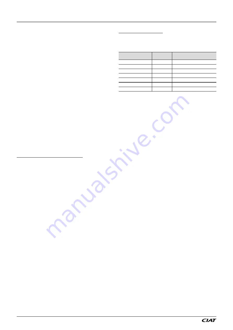
Safety device
(1)
Device for limitation of damage in
the event of an external fire
(2)
Refrigerant side
High pressure switch
X
External relief valve
(3)
X
Rupture disk
X
Fusible plug
X
Heat transfer fluid side
External relief valve
(4)
(4)
(1) Classified for protection in normal service situations.
(2) Classified for protection in abnormal service situations. These accessories
are sized for fires with a thermal flow of 10kW/m². No combustible matter
should be placed within 6.5m of the unit.
(3) The instantaneous over-pressure limitation of 10% of the operating pressure
does not apply to this abnormal service situation.
The set pressure can be higher than the operating pressure. In this case,
either the design temperature or the high pressure switch ensures that the
operating pressure is not exceeded in normal service situations.
(4) The classification of these relief valves must be made by the personnel
responsible for completing the hydraulic installation.
Do not remove valves / fusible plugs, even if the fire risk is under
control for a particular installation. There is no guarantee that
the accessories have been re-installed if the system is changed
or for transport with a gas charge.
When the unit is subjected to fire, a safety device prevents rupture
due to over-pressure by releasing the refrigerant. The fluid can
then break down into toxic residues when in contact with flames:
-
Stay away from the unit;
-
Ensure the personnel in charge of extinguishing the fire are
duly warned and issued with recommendations;
-
Fire extinguishers appropriate to the system and the
refrigerant type must be easily accessible.
All factory-fitted relief valves are lead-sealed to prevent any
calibration change.
The external relief valves must always be vented to outside if
the units are installed in a closed space. Refer to the installation
regulations, for example those of European standard EN 378
and EN 13136. These pipes must be installed in a way that
ensures that people and property are not exposed to vented
refrigerant. As the fluids can be diffused in the air, ensure that
refrigerant is discharged away from building air intakes, relief
valves must be checked periodically. The valves must be checked
periodically.
If the relief valves are factory-fitted on a changeover valve, this
is equipped with a relief valve on each of the two outlets. Only
one of the two relief valves is in operation, the other one is
isolated. Never leave the changeover valve in the intermediate
position, i.e. with both circuits open (move the lever fully forwards
or backwards depending on the output to be isolated). If a valve
is removed for checking or replacement, make sure there is still
a valve active on each of the changeover valves installed on the
unit.
Provide a drain in the discharge pipework, close to each relief
valve, to avoid an accumulation of condensate or rain water.
It is recommended to install an indicating device to check whether
any refrigerant has leaked from the relief valve.
The presence of oil at the outlet orifice is a useful indicator that
refrigerant has leaked. Keep this orifice clean to ensure that any
leaks are obvious. The calibration of a valve that has leaked is
generally lower than its original calibration. The new calibration
may affect the operating range. To avoid nuisance tripping or
leaks, replace or re-calibrate the valve.
AQUACIAT
POWER
ILD
EN-4


