background image

Содержание Conquest 1988

Страница 1: ...ecifications and tightening references Use of this manual will aid in properly performing any servicing necessary to maintain or restore the high levels of performance and reliability designed into these outstanding vehicles 2 Wiring Harness I Charging System _ Starting System _ _ _ _ _ _ _f_ _ _ _ i I Ignition System ti Lighting System E Wiper and Washer System orn _ _ Accessory _ _ _ _ _ _ _ __ ...

Страница 2: ...g the quality of a part or assembly on inspection or the value to which the part or assembly is corrected and adjusted It is given by tolerance LIMIT Shows the standard for judging the quality of a part or assembly on inspection and means the maximum or rninlmum value within which the part or assembly must be kept functlonally or in strength It is a value established outside the ranae of standard ...

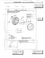
Страница 3: ...ake drum 2 Bleeder screw 3 Brake tube 4 Wheel cylinder assembly NOTE I IJ l 5 Wheel cyltnder boot Reverse the removal procedures to revwall 121 l Refer to Sewce Potnts of Removal l 6 PIstonassembly 3 l Refer to Serwce Points of Installation 4 l 7 PIstoncup 41 q Non reusable parts I 14wEQo SERVICE POINTS OF REMOVAL NOWBAA 7 REMOVAL OF PISTON CUP Using a screwdriver remove the piston cup from the pi...

Страница 4: ...try make vehicle type etc 2nd DigIt Make 5 4 Fremwm 3 door hatchbxk Englne N 2 6 hters I155 9 C I D I turbocharged engtne with rnteic uier number Z 000001 t Okazakl plant 99 E99 NOft hwk cimt means a slnqle number or letter X used IO verify the accuracy of trarrscrlptlon of vdhlcle Identlflcdtlon number VEHICLE IDENTIFICATION NUMBER LIST NOOCC V I N except sequence number Brand Package Destination...

Страница 5: ...545 T Tl Transmission model 4 COLOR TRIM H84 OPT I L Monotone exterior color code CHASSIS NUMBER NOOCE STAMPING LOCATION The chassis number is stamped on the top center of the firewall located in the engine compartment CHASSIS NUMBER CODE CHART A187MJZ000001 7 T VEHICLE SAFETY CERTIFICATION LABEL NOOCF The vehicle safety certification label is attached to face of left door pillar This label indica...

Страница 6: ...l is affixed to the following major engine transmission parts and body outer panels Engine cylinder bjock transmission housing fender quarter panel hood rear hatch and bumpers The theft protection label is also affixed to each of major body outer panels for servicing while the same informatioJ as the theft protection label is stamped on the engine and transmrs sion for servicing Caution 1 Affix ma...

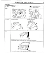
Страница 7: ...INTRODUCTION Vehicle Identification 7 LOCATIONS ransmlsston OOLO634 OOL0637 ...

Страница 8: ...ed to the inside surface l The illustration indicates left hand side outer Right hand side is symmetricaf 00L0640 l The theft protection label is affixed to the inside surface OOL0639 l The theft protection label is affixed to the inside surface r A _ Front bumper Rear bumper OOL0635 l The theft protection label is affixed to the inside surface OOLO636 _ ...

Страница 9: ...earances If an area having many parts similar parts and or parts which are symmetrical right and left is disassembled be sure to arrange the parts so that they do not become mixed during the assembly process 1 Arrange the parts removed in the proper order 2 Determine which parts are to be reused and which are to be replaced 3 If bolts nuts etc are to be replaced be sure to use only the exact size ...

Страница 10: ...rical system disconnect the I negative cable terminal from the battery Caution Before connecting or disconnecting the negative cable be sure to turn off the ignition switch and the lighting switch If this is not done there is the possibility of semicon ductor parts being damaged WIRING HARNESSES 1 Secure the wiring harness by using clamps However for any harness which passes to the engine orother ...

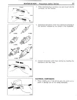
Страница 11: ...r not the harness 4 Disconnect connectors which have catches by pressing in the direction indicated by the arrows in the illustration 5 Connect connectors which have catches by inserting the connectors until they snap ELECTRICAL COMPONENTS 1 When installing any of the vehicle parts be careful not to pinch or damage any of the wiring harnesses ...

Страница 12: ...ate the cause of the problem before installing a new fuse 2 Check the condition of fuse holders If rust or dirt is found clean metal parts with a fine grained sand paper until proper metal to metal contact is made Poor Fontact of any fuse holder will often lead to voltage drop or heating in the circuit and could result in improper circuit operation 2 If additional optional equipment is to be insta...

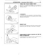
Страница 13: ...ordance with the instructions in this Service Manual apply the specified lubricants in the specified locations during assembly and installation BRAKE FLUID Be careful to avoid spilling any brake fluid on painted surfaces because the paint coat might be discolored or damaged c DOING SERVICE WORK IN GROUPS OF TWO OR MORE TECHNICIANS If the service work is to be done by two or more technicians workin...

Страница 14: ... so that external radro waves will not interfere with their operatron II zx e3 However If antenna or cable of amateur transceiver etc i z _ _ E routed near the computers It may attect the operationof the computers even rf the output ot the transcerver is no more G than 25W To protect each at the computers from Interference by rransmrtter hum transcerver etc the follow ing should be g observed z z ...

Страница 15: ...g a vehicle HOISTING POST TYPE Special care should be taken when raising the vehicle on a frame contact type hoist The hoist must be equipped with the proper adapters in order to support the vehicle at the proper locations Next page Conventional hydraulic hoists may be used after determining that the adapter plates will make firm contact with the front rear crossmembers FLOOR JACK A regular floor ...

Страница 16: ...Number of cylrnders Bore mm in 91 I 3 59 Stroke mm In 1 98 0 3 86 Piston displacement cm CID 2 555 155 9 2 555 155 9 Compression ratlo Firing order Manual transmissron Model No KM132 We 5 speed manual Gear rat10 Automatic transmrssr Model No We 4 speed automatic Gear ratio Reverse Dry single drsc Dry single disc diaphragm spring diaphragm spring mm G ma ...

Страница 17: ...87AMRFGL9 Al87AMNFGLS Front Rear Front Rear 205 55VR 16 225150VR16 205 55VR 16 225 50VR 16 225 5 Rl 6 24 R 16 225 506VR16 24514 R 16 Radial Radial Radial Radial Independent strut independent strut Independent strut Independent strut Disc Disc Disc Disc Integral type Integral type Recirculating ball nut Recirculating ball nut 14 3 14 3 Constant ratio gear Constant ratio gear 75 liters 19 8 gals 75 ...

Страница 18: ...1 25 14 x 1 5 16 x 1 5 18 x 1 5 213x 1 5 22 x 1 5 150 190 24 x I 5 PT 114 PT 318 Internal thread Aluminum Internal thread Cast iron Internal thread Aluminum Internal thread Cast iron Internal thread Aluminum Internal thread Cast iron nternal thread Aluminum nternal thread Cast iron NPTF 118 NPTF 114 ...

Страница 19: ...immer Control Switch 1 205 Headlight ___ __ 193 High Mounted Stop Light 200 Service Adjustment Procedures 190 Fog Light Aiming 192 Headlight Aiming _ _ _ __ 190 METERS AND GAUGES 157 Meters and Gauges _ _ 166 Service Adjustment Procedures 162 _ Engine Coolant Temperature Gauge Simple Test _______ __ 163 Engine Coolant Temperature Gauge Unit Inspection __ _ _ I_ _ __ _ _ 165 Fuel Gauge Simple Test ...

Страница 20: ... Door unlock relay ECI control relay ____ ECI control untt Fog Ilght relay ___c__ Hazard flasher unit __ Lighting relay ENGINE COMPARTMENT No la ____ Passing control relay __ ___I Passing relay for theft alarm sys _ Pop up relay Power window relay _II_ _____ Radiator fan air condltloner rel fiadiator fan motor relay Rear brake lock up control relay _ Rear brake lock up control unt __ Rear intermlt...

Страница 21: ...ELECTRICAL SYSTEM PARTS LOCATION Relav Control Unit Stal ter 7 2r windovl Y1i or Srelav iqht Lighting relay _ headlight T Defogger relay 1cv1sLLr INSTRUMENT PANEL 16Yi5371 ...

Страница 22: ...ELECTRICAL SYSTEM PARTS LOCATION Sensor INSTRUMENT PANEL ROOF LUGGAGE COMPARTMENT 16V2782 Photo sensor Foot area temperature sensor T Intenor temperature sensor L_ f ...

Страница 23: ... COMPARTMENT INSTRUMENT PANEL 7 T EC1684 I II 16Y35361 Symbol Diode for fog light circuit Diode for rear brake lock up control circuit D E Diode for theft alarm and automatic transmission circuit B Diode for theft alarm system circuit C Diode resistor A ...

Страница 24: ...CATION Inspection Terminal INSPECTION TERMINAL ENGlNE COMPARTMENT d INSTRUMENT PANEL Ignition timing adjustrng terminal Selfh3gnosis connector for ECI system autonlatlc speed control system automatic air condltloning and ETACSI ...

Страница 25: ... Fusible Link Fuse 8 9 FUSIBLE LINK FUSE ENGINE COMPARTMENT m q INSTRUMENT PANEL EC1684 Dedicated fuse 1 I E for heated remote controlled mirror Main fusible link _ _ Multi purpose fuse A E Sub fusible link 1 D Sub fusible link 2 B I ...

Страница 26: ...ELECTRICAL SYSTEM PARTS LOCATION Groundina GROUNDING ENGlNE COMPARTMENT LUGGAGE COMPARTMENT INSTRUMENT PANEL FLOOR 16Y154C I _ I ...

Страница 27: ...ELECTRICAL SYSTEM PARTS LOCATION Grounding i I 36Y51 ...

Страница 28: ...GEMENT OF TER MINAL When terminal stopper of connector is out of order engage ment of male and female terminals becomes improper even when connector Aself is en gaged perfectly and terminal sometimes slips lout to rear side of connector Ascertain therefore that each terminal does not come off connector by pulling each harness wire ENGAGING AND DISENGAGING OF CONNECTOR 1 TERMINAL w Connector which ...

Страница 29: ...aise housing lance slightly with it and pull out harness NOTE Tool No 753787 l supplied by AMP can be used instead of screwdriver 4 Insert needle through a hole provided on terminal and raise contact point of male terminal ROUND WATERPROOF CONNECTOR 1 Remove waterproof cap by using a screwdriver 2 Insert tip of screwdriver I4 mm 06 in or 20 mm 08 in width as shown in the figure raise housing lance...

Страница 30: ...nnector in a manner as shown In the figure push it lightly G to raise housing lancer and pull out harness If right size screwdriver is not available convert a _ Em conventional driver to suit the size _ _ _ _ 3 Press contact point of male terminal down by holdiqa __ screwdriver I 4 mm 06 in width in a manner as shown in the figure 1 _L INJECTOR CONNECTOR LZ r 1 Remove waterproof cap 2 Insert tip o...

Страница 31: ... Harness Connector 8 15 16R1327 3 Press contact point of male terminal down by holding a screwdriver I 4 mm 06 in width in a manner as shown in the figure Caution Correct lancer to be in proper condition before terminal is inserted into connector ...

Страница 32: ... is carried out by making step by step checks until the true cause Is found Always go through the procedures considering what check is to be made where for the best results After the problems are corrected be sure to check that the system operates correctly Also check that new problems have not been caused by the repair information for diagnosis This manual contains the cable diagrams aswell as th...

Страница 33: ... light to the body by a jumper wire to determine which part is responsible for the problem 3 CHECKING WITH INSTRUMENTS Use an appropriate instrument in an adequate range and read the indication correctly You must have sufficient knowledge and experience to handle instruments correctly INSPECTION INSTRUMENTS In inspection make use of the following instruments 1 TEST LAMPS A test lamp consists of a ...

Страница 34: ... Normally the positive red lead probe is applied to the point of voltage measurement and the negative black lead probe to the body ground 5 OHMMETER An ohmmeter is used to checkkcontinuity or measure resistance of a switch or coil If the measuring range has been changed the zero point must be adjusted before measurement CHECKING SWITCHES In a circuit diagram a switch is represented by a symbol and...

Страница 35: ...magnetized to attract the iron piece closing ON the contact at the tip of the iron piece When the coil current is turned off the iron piece is made to return to its original position by a spring opening the contact OFF 2 By using a relay a heavy current can be turned on and off by a switch of small capacity For example in the circuit shown here when the switch is turned on closed current flows to ...

Страница 36: ...4 Disconnect the load at the connector and connect the test lamp lead wire to the load side of the connector 0 The test lamp should come on and the load lamp should also come on 5 Connect the test lamp lead wire to the switch side of the connector I The test lamp should come on 6 If the test conforms to any of the above conditions there is a shortcircuit in the wiring between the connector a and t...

Страница 37: ...or color Connector s unique number serial number Connector symbol A Engine compartment B Dash panel C Interior D Instrument panel E Luggage compartment F Rear hatch A 07 Radiator fan motor A 08 A 09 Headlight right Washer fluid level sensor A IO A l 1 Side marker light right Front washer motor A 12 Rear washer motor The first letter A of the connector symbol indicates that the connector is located...

Страница 38: ...wer case alphabet after a serial number For detailed information on this specrflcation dependent symbol refer to liem 8 under HOW TlCf REAP CIRCUIT DIAGRAMS 31 Indication of standard mounting positions of harnesses The standard mounting positions of harnesses are shown with the mark in wiring harness configuration diagrams 4 Indication of ground point The position of ground points are shown In wir...

Страница 39: ... symbol corresponds to the symbol in a wiring harness configuration diagram so that the connector location can be known easily An intermediate connector has its female side only shown as a rule However both of the male and female sides are shown when they differ in wiring color If a frame showing a connector touches the symbol of a device it indicates that the device IIRefer to Items 2 and 3 The f...

Страница 40: ...point in a circuit diagram is marked by a GND symbol making it possible for you to refer to a wiring harness configuration diagram and to ELECTRICAL SYSTEM P RTS LOCATION GrouFding 6 Indication of wires In a circuit diagram the wire diameter and wire color are shown for each wire If there are several wires of the same color In a connector their wire color indication symbols should be such symbols ...

Страница 41: ...ation dependent connector identification symbols lower case alphabet following the connector symbol Example A 01 a T Specification dependent connector identification symbol a Vehicle with manual transmission b Vehicle with automatic transmission 9 Shapes of connectors The connector shapes are indicated by simplified symbolic marks For distinction between male and female connectors refer to IDENTIF...

Страница 42: ...ale connectors Connectors drawn with double outer lines are male and those with single outer lines are female 3 Connector direction a The connector _ marks shpw on vehic1 e donneqtors as F viewed from the direction shown here 4 Identification tif connector_ terminals The color codes of a pair of connectors male and fe male if __ viewed at their joining surfaces will appear symmetrical as illustrat...

Страница 43: ...n circuit diagrams as shown below Battery Body ground Single bulb Resistor Diode Capacitor Ii3 d k J 1 1 1 t T 7 Fuse Equipment Dual bulb Variable resistor Zener diode Crossing of wires ground without connec tion 0 s rl 0 x 17 4 Fusible link Motor Speaker Coil Transistor Crossing of lines with connection Q pj ...

Страница 44: ... wire 1 When cross sectional area IS not Indicated the area IS 0 5 mm 2 Cross sectional area Indicated by in cable color IS 0 3 mm 1Code Wire color 1 Code Wire color I I L I Light blue I Br I Brown I 0 I Orange I I G I Green I p I Pink I I Lg I Light green I w I White I NOTE If a cable has twb colors the f st of the two color code charact rs indicates the basic color color of the cable coatinaand ...

Страница 45: ...WIRING HARNESS Wiring Harness Overview 8 31 Wiring Harness Overview NOBDC ...

Страница 46: ...lay Brake fluid level sensor Theft alarm horn relay Condenser fan motor relay vehrcles with arr condrtroner A 01 Radrator fan AK relay Z tvehrcles with arr conditioner Magnet clutch relay rvehrcles with air conditioner Radiator fan A C relay 111 vehicles with air condrtroner Resrstor I Ignition co11 Front harness and control harness combination A 09 A 10 A 33 Front harness and alterna A 34 Fusible...

Страница 47: ...enser fan motor vehicles with air conditioner Dual pressure switch Pressure switch vehicles with air conditioner Horn high A 50 A 47 5 A 26 A 37 f A 36X A 42X 1 3 A 2 4 Remarks 1 The mark shows the standard mounting position of wiring harness 2 For details of grounding points ex 8 refer to page 8 I C 3 _ means that the connector with corresponding code number is not used 36Y5E ...

Страница 48: ... spark control lgnlter A 78 Magnet clutch A 79 lgnltlon co11 A 80 Maln fusible llnk A 81 Fusible link box A 82 Relay box A 83 A e4 Alternator A 85 011 pressure gauge unit A 86 Detonation sensor A 87 Secondary air control solenoid valve A 88 EGR control solenotd valve A 89 Engine coolant temperature switch A 90 Engine coolant temperature sensor A 9 1 Engine coolant temperature gauge unit A 92 Dstnb...

Страница 49: ...WIRING HARNESS Engine Compartment 8 35 A 68 A 73 A 78 I A 84 36Y 56 ...

Страница 50: ...front harness and arr condrtioner harness combrnatron B 63 B 64 Servo motor B 65 B 66 B 67 B 68 B 69 B 70 B 71 B 72 B 73 B 74 B 75 B 76 B 77 B 78 Vacuum solenord valve Blower motor starter cutout relay Vacuum solenord valve Foot area temperature sensor Power transistor No connectron or arr condtttoner harness and rear harness comhrnatron Light controller Blower motor hrgh speed relay Air flow sens...

Страница 51: ...WIRING HARNESS Dash Panel 8 39 B 61 B 62 B 63 B 64 B 96 B 67 B 68 B 69 B 70 B 71 1 Remark means that the connector with corresponding code number is not used 361563 ...

Страница 52: ...atron C 16 Remote controlled mtrror R H C l 7 Power wrndow swatch R H C 18 Door key cylinder unlock switch R H C 19 Door lock switch fR H C 20 Door lock actuator R H C 21 Fasten swatch R H C 32 c 31 c 30 c 22 C 23 C 24 C 25 C 26 c 27 C 28 c 29 c 30 c 31 Root harness and rear harness combrnatron Door swatch H H Motor R H Door light R H Door speaker R H Power wIndow motor R H Buckle switch Front har...

Страница 53: ...25 C 24 C 23 C 41 Spool release lever switch C 42 Ashtray illumination light C 43 Parking brake switch Remarks I The mark shows the standard mounting position of 2 wiring harness For details of grounding points ex q refer to page 8 l 0 36Y564 1 C 42 ...

Страница 54: ...er L H I D 02 Dimmer control switch D 03 D 04 Defogger switch D 05 I D 06 Rear wiper and washer switch D 07 Front harness and glove box harness comblnatlon D 08 D 09 Cigarette lightel D IO I D l 1 Glove box switch D 12 Glove box Illumlnatton light D 13 Front speaker H H 1 D 14 SelfdIagnosE connector D l 5 Ashtray illumlnatlon light ...

Страница 55: ...ation light R H E l 1 Fuel gauge unit E 12 Rear hatch switch E 13 Rear hatch key cylinder unlock switch E 14 License plate light R H E 15 Rear intermittent wiper relay E l 6 Joint connector E 17 Rear harness and fuel gauge unit harness combination E 18 Rear harness and license plate light harness combina tion E 19 License plate light L H E 20 Motor antenna relay E 21 Rear combination light L H E 2...

Страница 56: ... window defogger combina tion F 02 Stay switch L H and high mounted stop light harness combination F 03 Stay switch L H and rear wrper motor combination F 04 High mounted stop light F 05 Stav switch R H and rear wiper motor combinatron F 06 StaTs F litch R H and rear window defogger combina tion ...

Страница 57: ...3 IAL unrr Remarks 1 Dashed line shows wiring for vehicles with a manual transmission 2 r Dot and dash line snows wlrlng TO vehicles with an automatic tran 511115 sion For details of grounding points ex Inhibitor Starter inhibitor 3 switch relay 37Y604 I refer to page 8 10 Wire color code B Black Br Brown G Green Gr Gray L Blue Lg Light green LI Light blue 0 Orange P Pink R Red Y Yellow W White ...

Страница 58: ...o InhIbItor swrtch Vehicle with autorndtlc transnllsslon Waste gate solenoid fi valve 6LR Sub fusible ci llnk 2 remark Battery ECI control unit 1 25 B m 0 85 B El or details of grounding points ex W efer to page 8 l 0 A 66 lgnltlon timing adjusting terminal A 92 Wire cnlnr cnrie _ _ _ 6 Black Br Brown G Green Eiectrorilc spark control rgnlter Deto ion Ulstnbutor sensor slgnal generator R Red W Wht...

Страница 59: ... Multi purpose fuse _ tail light I Battery I I UI SIS LK d B 23 7 I Combination meter relay I Resistor B l Remark I refer For details of grounding points ex to page 8 I 0 I I I IL regulc A Wire color code B Black G Green Gr Gray LI Liqht blue 0 Oranqe P Pink W White Lg Light greer Y Yellow Alternator 37Y60 ...

Страница 60: ...I SYSTEM CIRCUIT Vehicles with Manual Transmission lgnltlon switch Comblnatlon meter To turn signal flasher unit tvlultl purpose fuse 6 _ Z BY 7 I YG 19 To compressor Refer to P 8 761 Battery To AK compressor relay Refer to P 8 761 1 25 B Ia I I B 30 ECI control relay heck connector I i i 37YS84 ...

Страница 61: ... I I 1 I I I I I I I I I I I I I 04 WR 5 u A 29 A 3 Ignition coil Detonation sensor I 1 Electronic spark Air flow sensor UlstrlDutor signal generator control igniter BY GT w B VI B iregx code Br Brown Gr Gray L Blue LI Light blue 0 Orange R Red W White G Green Lg Light green P Pink Y Yellow ...

Страница 62: ...valve sensbr B 36 I 1 25 R t 992 1 2 813 0 85 B RW ECI control unit 51 _ 52 53 54 55 56 57 58 59 60 61 62 63 1 2 3 4 5 6 7 10 11 12 13 14 15 16 19 20 21 22 23 0 85 0 85 RB I I I 6 2 R I I I I I I I I Ignltlon tlmlng 6 adlusting terminal Remarks II I For detz311sof grounding points cx HI 7 l 0 _ retcr to page t 71 Thn clrclllt IlnF Motor posrtron Engine coolant Throttle _ n ...

Страница 63: ...witch Combination meter Multi purpose fuse I I I CBR I I I I 1 25 R n 2 BW a Z BY A BW 1 25 BR r Z BY Dg VP 2 M I I c 4 IA I F e Sub fusible IA 341 Battery Inhibitor switch PN 333zn 2 BR 1 I I Z BY WIBY A 20 t ttt To compressor Refer to P 8 761 T I 1 I I 1 2 p 1 1 3E R T m d 1 I I ECI ontrol relaye30 L D1 I 2 BW 2 d w E 17 E 24 r c 7 Fud pump ...

Страница 64: ...e lb 13 WR l i r _ ___ 171 I I l 30 r l r _ spark Detona on Dlstnbutor cIeLL lIIL sensor smdl acnerator rnntrol Ign g FL I _ 1 Air tlow sensor Wire color code B Black Br Brown G GEW Gr Gray L Blue LI Light blue 0 Orange Lg LlCJhl green P Ptnk R Red W White Y Yellow s i i i J lgmtion co11 ...

Страница 65: ...WR 1 I I I I I IL 1 I For details of grounding points ex H Ignition timing 1adjusting terminal 3 3 Remarks Motor position sensor Engine coolant temperature seni Throttle reter to page 8 l 0 position 2 The circuit lines ended with number i l sensor Jand so on are in continuation to those with the corresponding number on on the right hand page opposed page i e the line ci on the left hand page IS co...

Страница 66: ...54 WIRING HARNESS ECI System Circuit ECI SYSTEM CIRCUIT CONTROL PARTS LAYOUT 5FUOO56 lF fI E l684 Air flow sensor with built in atmospheric nsor and intake air tempera Inhibitor switch vehicles with an automatic transmission ...

Страница 67: ...WIRING HARNESS ECI System Circuit 8 55 ECl6cz j EC1691 ...

Страница 68: ...8 56 WIRING HARNESS ECI System Circuit A r condlttoner switch I Boost meter ...

Страница 69: ...WIRING HARNESS ECI System Circuit 8 57 ...

Страница 70: ...itch Therm0 sensor Therm0 sensor No 2 Radiator fan motor No 2 A 07 I Radiator fan motor relay No 2 Radiator fan motor relay No 1 Remark For details of grounding points ex R refer to page 8 10 LB81 El G B LB L1 El3 BY8 JVire color code 3 Black Br Brown G Green J Light blue 0 Orange P Pink Gr Gray R Red ...

Страница 71: ...nrt Diode a5 Kick down switch I Over drive solenoid Over drive solenoid Br uo a RW UU 0 A 19 Q Down shift solenoid a r B 07X 1 To dimmer control switch Refer to P 8 66 1 Over drive relay Wire color code B Black Br Brown G Green Gr Gray L Blue Lg Light green emark R F rc or details of grounding points ex g fer t0 Page 8 10 LI Light blue R Red 0 Orange W White P Pink Y Yellow 37Y597 ...

Страница 72: ... LW 2 LYI 2 LY I 1 La g u 2 LY GL 2 B A 38X L lgnltlon switch Passlnq relay k 2 I motor IL H 1 Cluster switch IL H tLqhtlng 371609 27 Wire color code B Black Br FGwn G Green Gr Gray L Blue Lg Light green Lpi l k the 7 marlgb W White Y Yellow Cluster switch Passitiq con l relay R H 1 Pop up emark 3r details of grounding points x J refer to page 8 I 0 ...

Страница 73: ...0 85 L R Z LW Cluster B 20 switch L H I Multi purpose fuse B 23 A 2 1 0 85 LW y 0 85 LY 1 Passing relay wire color code Head light L H Head light R H Z cx B 39 B 22 f j Combination meter Passing relay Column switch Remark For details of grounding points ex refer to page 8 10 3 Black Br Brown y 8 pd L Blue Lg Light green I Light blue 0 Orange W White Y Yellow ...

Страница 74: ... 34 RnR Fnn ltnht F J3 wl3 Ignltlon switch mI0 85 LY 2 LW I I I reT A 36 r Fog light IL H D ode To headlight s Refer to P 8 61 I I tn N I s i RY A 21 Passing relay Colurnn switch Passing control relay 37Y594 _l I _ Remark For detarls of grounding points ex I refer to page 8 10 Wire color code 6 Black Br Brown ti Green LI Light blue 0 Orange P Pink y y L Blue Lg LIght green W White Y Yellow i KZ f ...

Страница 75: ...IRI Batter Cluster switch L H gg GW E 14 n m License Side marker I Tail I I I light R H Position I I I I I I I I Rearzombination light R H L 0 EEH ew B II Tail marker GW 43 Y Front A 67 combination light L H Position I I ill Rear combination light L H Srn iii A 6 1 A 46 Side marker linht I H 1 Side marker linht IR H 1 a I I J a 37159 Wire color code B Black Br own G Green Gr Gray L Blue Lg Light g...

Страница 76: ...on light L H Hear combinatron light R H Remarks 971590 I Dot and dash line shows wiring for vehicles with a manual Wire color code transmission B Black Br own G Green e 0 I I 2 Dashed line shows wiring for vehicles with an automatic Gr tiray L Uue f g Lrgnr green transmission LI Light blue 0 Orange P PPnr 3 For details of grounding points ex m refer to page 8 l 0 R Red Y Yellow W White i ...

Страница 77: ...1 u c 22 ct I E l 2 n Multi purpose fuse lw Rear hatch I switch 1 B 23 B 31 Combination I 2 connector D 14 D 07 E Door light R H B l 3 4 t c 3 n D n YB I I I I I I I RB 0 RB Iemark TAC unit Door light L H or details of grounding points ex m refer to page 8 l 0 Jiregc r code f Light blue Br Brown G Green 0 Orange Gr Gray P Pink R Red L Blue Lg Light green W White Y Yellow ...

Страница 78: ...usible link 2 El IBattery Multi purpose fuse mm BY I 3 0 OYl 0 85 8 0 85 B d I BY I CWI I cw 0 85 B g r l 1 D 02 up U La _ 1 I 1 PTf By D 07 I I Dimmer control switch I 08 Defogger switch illumination light r 5 r 5 r Ash tray 16 if Cigarette lighter illumination light switch light I Combination illumindon light meter ...

Страница 79: ...ight J GWm Vanity mirror illumination light R H C 08 Ret I marks 0 c Vanity mirror illumination light L H 2 The circuit lines ended with nurnbe KJ and so on are in continuation to those with the corresponding number on opposed page i e the line on the left hand page IS connected to the line on the right hand page For details of grounding points ex E refer to page 8 l 0 El 0 Wire color code 0 B Bla...

Страница 80: ... Combrnation meter I A 57 A 01 E 21 H Retnark Turn Turn For details of grounding Hazard L H 1 Hazard R H 1 Turn Hazard CL H 1 Turn Hazard R H P 2 pornts ex 8 refer to paae 8 10 Front combination light Rearcombination light WL lFEE3 WR 3TYSTT Mre color code Ei B L l ue m LG Light green 3 Black Br Brown G Green _I Light blue 0 Orange P Pink W White Y Yellow ...

Страница 81: ...d Sub fusible link 2 3 LA i Battery High mounted stop light B 51Grl q Cluster switch switch L H Stop L H Stop R H V Rear combination light Remark For details of grounding points ex R refer to page 8 I 0 WR EEQ B Wire color code B Black Br Brown G Green L Blue LI Liqht blue _ Gr Gray Lg Light green 0 Oranqe P Pink R Red W White Y Yellow _ 371578 ...

Страница 82: ...nitlon switch To radio remote control switch Refer to P 8 87 1 B 51 Horn switch Remark For details of grounding points ex 8 refer to page 8 I 0 Wire color code B Black Br Brown G Green I pdY Lr Blue LI Light blue Lg Light green 0 Orange P Pink Y Yellow W White ...

Страница 83: ...ion meter 0 I To ECI control r usible unit To alternator or 7 m I ml I II zI 55 1Battery To ECI control unit J J ITI I m 3 El Jine coolant Oil pressure For details of grounding points 1 refer t0 page 8 l 0 ex B Remark Ignition coil Wire color code En B Black Br Gr Gray L LI Light blue 0 R Red Y Brown 3 Green Blue Lg Light green Orange P Pink Yellow W White ...

Страница 84: ...ding points ex I refer to page 8 l 0 The circuit lanes ended with number ii 6 1 and so on are in Wire color code B Black Br Brown G Green contrnuation to those wrth the correspondrng number on L Blue opposed page i e the line 1 on the left hand page IS Cr Gray LgL4tg xgeeC _ _ L1 Lrqht blue 0 Orange P Pink connected to the ltne 1 1on the right hand page R Red W Whrte Y Yellow ii ge q 2 ...

Страница 85: ...NESS Power Window Circuit 8 73 Power window relay X Power window main switch Power window motor L H 5 C 36 j B 09 1 I Power windnw _ motor R H C 23 _I 27 t t k 27 L H R H Door switch Power window sub switch 37Y5 ...

Страница 86: ...lock actuator L H Battery Sub fusible link 2 l I E I 1 0 Ai22 2 J To motor antenna relay 4 o 85 Lo Door switch L H D l4 Self diaanosls connectuor i 11 1 37Y6OC Gr Gray L Blue R Red W Whrte Remark For details of grounding points _ ex EW refer to page 10 Lg Light green Y Yellow 7 llL7 C l l b YC Black Light blue Green Pink Br Brown G 0 Orange P ...

Страница 87: ...tor B 62 j m I L 8 m m I I I N N Ej R B ELB 1 25 LY 1 25 LY 0 85 LW 0 85 LW Resistor i I II I I I 1 II I 0 Blower switch Remark r I r t or aetalls OT grounding points ex W refer tc1page 8 l 0 37Y5 89 Wire color code Bi Black Br Brown G Green Gr Gray L Blue Lg Light green LI Light blue 0 Orange P Pink R Red Y Yellow W White ...

Страница 88: ... relay I 1 25 B TWL is I I I10 Blower relay Power transrstor notor y B 70 Remarks 1 The circuit lines ended with number 1 2 1and so on are rn contrnuatron to those with the correspondrng number on opposed page i e the lrne 1 1 j on the left hand page IS connected to the line j on the right hand page 2 For details of grounding points ex a refer to page 8 10 Wire color code B Black Br Brown G Green ...

Страница 89: ...I 1 El 2i d Ignition switch Engine coolant Photo temperature gauge sensor B 6 64 LB a u c L 0 I I l B 62 634 3 LB 04 Lw ii m L omo D 07 0 jB 75 B 7 0 1 I 1 2 Automatic air conditioner control unit I I Self diagnosis connector 3 B a 37Y582 D 07 GI I I I I I I I I 7 15 5 ...

Страница 90: ...rm0 sensor Radiator Thermo Radlafc fan motor sensor fan mo No 1 No 2 No 2 No I C Pressure switch A 58 CL A 78 B 0 85 BW m II u I u a 3 5s c A 26 Self dlagnosls connector Radiator fan motor relay No 2 Radiator fan Radiator fan Condenser Magnet air conditioner air condltloner fan motor clutch relay relav 2 relay I 1 relay ...

Страница 91: ... Conditioner Circuit AUTOMATIC AIR CONDITIONING SYSTEM CONTROL PARTS LAYOUT 8 79 Condenser fan motor relay 1 B t Radrator fan air conditioner relay I 1 2 I B Dual pressure switch Engine coolant temperature sensor Engine coolant temperature switch E Radiator fan motor relay 1 2 F A Solenoid valve No 1 K A Solenoid valve No 2 No No 4 I Foot area temperature sensor L Thermistor M I Interior temperatu...

Страница 92: ...WIRING HARNESS Air Conditioner Circuit INSTRUMENT PANEL q L d unit r 2OY1646 I I I l Foot area te perature sensor 36YO14 20 1 a5 _ 2oy1635 E Is r ...

Страница 93: ...WIRING HARNESS Air Conditioner Circuit 8 81 ROOF 7 Interior temperature sensor w ks l rrl t 2OY184 ...

Страница 94: ...Wiper and Washer Circuit Multi purpose fuse ub fusible nk 2 Battery To automatic seat belt control a7 c 1 d Wiper relay vvasner t ront fluid waFL I T Remark level El For details of grounding points sensor L t iex HI refer to page 8 I 0 EL B LI Vw color code I Black Br Brown G Green g y L Blue 1 Lqht blue 0 Orange Lq Llqht green P Pink W White Y Yellow 37Y57E ...

Страница 95: ...tch R H Y Multi purpose r l u w fuse 4 _p I z E l 6 t To front t w II II t 2 wiper motor mL am 1 Sub fusible link 2 Battery D 3 G l r e E 08 I INT OFF ON m If M c Rear washer motor Rear wiper and washer switch 37Y575 Remark For details of grounding pornts ex m refer to page 8 10 r a or code Br Brown G Green r pJdy L Blue Lg Light green LI Light blue 0 Orange P Pink W White Y Yellow ...

Страница 96: ...elt control unit I Tr i nmc t r LRI 1 I I au LVIIIcIIIb AC control unit u OL KL ttti Tfiurn signal m flnshpr init Refer to P 868 1 z A B l 1 lemark I or detaarls of groundrng pornts 3x R refer to page 8 10 I I Stay swatch R H I 1 2 BRC 2 B I E 04 2 B I m E 02 id wrtch 371805 I I I A 42X _ J Defogger relay E Wire color code B Black Br Brown G Green Gr Gray L Blue Lg Light green LI Lrght blue 0 Oran...

Страница 97: ...y Ignition twitch Main A 80 fusible link El 3 LA LO El 0 Sub fusible link 1 B M CA B 41 Buzzer r L 0 85 LO I B T To automatic B seat belt 4t control unit LR To automatic A C control unit 0 85 RL To turn t signal flasher unit M t4 I T El cc c 34 n T n Ra LR B I I I I A 42X TAC unit Defogger relav ...

Страница 98: ... on opposed page I e the line 1 1on the left hand page IS connected to the line I ton the right hand page Defoouei switch Remote controlled mirror L H w M M D 14 connector B 09 B 3 I I6 LR 0 85 B 5 I CIL L IC n t LL 3 2 B 4 4 2 BR r 5 0 85LB il Remote controlled mrror R H Mi olled mirror switch Remote cot ItI Wire color code B Black Br Brown G Green Gr tiray L Blue Lg Light green LI Light blue 0 O...

Страница 99: ...ont speaker R H L H Refer to P 8 66 1 Ignition switch L I lil kl IG1 ACC B 48 I II 34i Multi purpose c fuse e 10 85 L To turn signal flasher unit Battery c 0 a 1B 44 1 Amplifier r 1 Radio 4 To horn switch Refer to P 8 70 1 Radio remote control switch ...

Страница 100: ...ing points ex a refer to page 8 I 8 2 The circuit lines ended with number 0 I and so on are In continuation to those with the corresponding number on opposed page I e the lrne on the left hand page is connected to the lrne i on the right hand page Wire color code B Black Br Brown G Green g yaJ L Blue _ Lg Light green LI Light blue 0 Orange P Pink 417 Yellow W W hite WY572 ...

Страница 101: ...sible CA i t c link 2 J 5 w 3 w D 07 0 85 l W n 0 85 LW 0 85 B I I 0 85 B Wire color code B Black Br Brown LI Light blue 0 Orange LOCK cc B 48 Vl Ei purpose IB 29 Clock Cigarette lighter Remark For details of grounding points ex H refer to page 8 10 L Blue Y Yellow Lg Light green W White 37Y570 i G Green P Pink Gr Gray R Red ...

Страница 102: ...se b urr1 slgnal flasher 0 85 R 4 Modulator Re jr brake lock uo control relay p q L_ Pulse generator r 3 Remark For details of grounding points iex l refer to page 8 10 Stop light B 54 switch ResIstor switch 1R H I Rear brake lock up control unit 01 Wire colorczodc B Black Br Brown G tireen 37Y595 WG GW I 1 I I I u Gr Gray 1 Blue LI Lloht blue 0 Oraye 9 a green R Red W White Y Yellow ...

Страница 103: ...uit REAR BRAKE LOCK UP CONTROL SYSTEM CONTROL PARTS LAYOUT Name Symbol Name Symbol G sensor Modulator Pulse generator F Rear brake lock up control relay C A Rear brake lock up control unit E D Resistor B ENGINE COMPARTMENT q INSTRUMENT PANEL EC1684 ...

Страница 104: ...gg WIRING HARNESS Rear Brake Lock up Control Circuit ar TRANSMISSION LUGGAGE COMPARTMENT ...

Страница 105: ...1 l ILU To resistor I I Multi purpose fuse Actuator A l 1 Ia I B 54 A a ys 1 0 85 G 0 I U WV g 85 GW top light switch 0 85 i 0 85 GW tg 0 85 B J IB1 P G WR WL 0 85 GW 0 85 WG z A 52 A I Column switch Vacuum pump relay Q pJyJ lZ m I I Turn signal switch I I WC WR WL 0 I I I I I I I L U Vacuum pump ...

Страница 106: ...rssron 3 __ For details of grounding points ex I refer to page 8 10 T r cled with number 1 and so on are rn 1F 23 contrnuatron to those wrth the corresponding number on PI I I opposed page i e the ltne I 1on the left hand page IS connected to the Irne I eon the right hand page g 1 B Black Wire color code Er Brown G Green speed control unit G Gray li_ Blue Lg Light green Cluster swatch iAm L d blue...

Страница 107: ...LAYOUT N14ED A Name Symbol Name Symbol Actuator I B I Electroni c control unit ECU I G I Brake switch I I I E Vacuum pump C Clutch switch Vehicles with manual transmission F Vacuum pump relay A Diagnosis t minal D Vacuum switch A ENGINE COMPARTMENT INSTRUMENT PANEL EC1684 z2BT i lum switch ...

Страница 108: ...8 96 i WIRING HARNESS Speed Control System Circuit LUGGAGE COMPARTMENT El ...

Страница 109: ... fuse B 01 I I I switch 3 WB a C 24 Key reminder switch Buckle switch L H srde R H side Y J Motor T L circuit lines ended with number and so on are in continuation to those with the corresponding number on opposed page i e the line on the left hand p age is connected to the line on the right hand page 2 For details of grounding points ex I refer to page 8 l 0 ...

Страница 110: ... KL l I II I 2 l I 85 RL 1 RL 1 85 LO I 3 LW RR B 09 I I KG11 Ilr I I RB I 1 R I 1 B 31 c3rnoC LLLJ c 21 I I I I lc 19 c 13 Release switch Fasten switch R H 1 u w iR H Door lock switch Wire color code if3 H Slrk 37Y599 B Black Br Brown G Green Gr Gray L Blue_ Cl tght blue 0 Orange P Pmk Lg Light green R Red W Whrte Y Yellow ...

Страница 111: ... mcJ 37Y583 El Starter motor r l 7 l 1 m l C Inhibitor _ swi El Remarks 1 Dashed line shows wiring for vehicles with a manual transmission 2 Dot and dash line shows wiring for vehicles with an A 4 automatic transmission 3 The circuit lines ended with number 3 3 and so on are in continuation to those with the corresponding number on opposed page i e the line on the left hand page is connected to th...

Страница 112: ...itch R H I I I I I I I Combinatlon meter Theft alarm indicator Passing relay Passing control relay I A 2 B 3 B 23 j r To column switch 4 RB 1714 0 85 LY 8i4 BG A 09 K A IO A A 2 Theft alartn horn relav Theft alarm horn Hood switch Diode Pop up motor L H 1 J ...

Страница 113: ...or Door lock switch L H aCtuator Rear hatch switch Self diagnosis connector q Y D l 4 I E 12 TAC unit 2 F 7B l5_ B 33 WI 1 u c E 16 w 03 18 E l d u A r r Q Q Rear hatch key cylinder Y unlock switch Door key cylinder unlock switch pi g 37Y589 ...

Страница 114: ...ogger Power window circuit Wire color Black mm 1 25 I Size i in Go 0 0019 ES Sub Fusible Link 1 Sub Fusible Link 2 Dedicated Fuse Item High beam circuit Fog light circuit Heated remote controlled mirror circuit No 1 2 Rated capacity A 5 15 5 Circuit Breaker Item Rated capacity A Automatic seat belt circuit 20 ...

Страница 115: ...circuit Automatic seat belt Clock Radio Door light TACS Theft alarm 11 12 13 IO 10 10 Radio Clock Power antenna Rear brake lock up control relay Blower relay Defogger relay Air conditioner Turn signal light Meter and gauge Remote controlled mirror Power antenna ETACS Automatic seat belt 14 10 Alternator Back up light Overdrive relay Speed control switch ...

Страница 116: ...tion symbol Part name E Turn signal flasher unit m interior T z B 03X Hazard flasher unit rrr Rear brake lock up contra B 05X 1 Door unlock relay A 45X Pop up motor relay R H I h Engine compartment relay box 5 I I A 38X liila A WX A 40X I 16 13564 Sub fu sible link 1 s through Fusible lank box A 41X A 43X A 42X Sub f ble link 2 16Y3576 I 0wmw ...

Страница 117: ...WIRING HARNESS Centralized Junction Interior relay box Multi purpose fuse through B 05X E B v 16Y3578 B 06X WRRLB RTl I I I L R LWLR Fuse check ligh B 07X Interior fuse box 2 16Y3563 2OY809 ...

Страница 118: ... rectifiers three posrtrve and three negative each rectrfyrng AC current to DC current Therefure DC current appears at the alternator BY terminal This alternatorregulates charging voltage by detecting battery voltage The main compunents of the alternator are rotor stator rectifiers capacrtors brushes bearingsand V ribbed belt pulley The brush holder has a built in electronic voltage regulator i I ...

Страница 119: ...k assembly Is PI Stator W t ed belt 6EL240 6EL211 MAINTENANCE FREE TYPE BATTERY 1 The maintenance free battery is as the name implies totally maintenance free and has no removable battery cell caps 2 Water never needs to be added to the maintenance free battery 3 The battery is completely sealed except for small vent holes in the cover ...

Страница 120: ...RANKING RATING IS the current a battery can deliver for 30 seconds and marntarn a termrnal voltage of _ 7 2 or greater at a specrfred temperature 2 RESERVECAPACITY RATING is the amount of trme a battery can deliver 25A and marntarn a minimum terminal voltage of 10 5 at 26 X 80 F SERVICE SPECIFICATIONS NOBEG Items Standard value Regulated voltage V Ambient temp at voltage regulator Slip ring O D rn...

Страница 121: ...HARGING SYSTEM SDecifications TORQUE SPECIFICATIONS NOSED Items Nm ft lbs Alternator support bolt and nut 20 25 14 18 Alternator brace bolt 12 15 9 10 Discharge hose 20 25 14 18 Suction hose 30 34 22 26 ...

Страница 122: ...3 R A81 J pose fuse I 03 KL 1 I To turn signal flasher unit Battery I I D LJ Comblnatrorl meter 3 R To tall hgl It relay Remark I For dctalls of grounding points ex I refer to page 8 10 Wire color code B Black Br Brown G Green Gr Gray LJ Light blue L Blue 0 Oranqe Lg Light 91 P Pink IL layuldlul 1 R R f W Whtte Altr rnator ...

Страница 123: ... current thus controlling the current the alternator generates l Once the alternator starts generating current a voltage slightly higher than battery voltage is applied to L terminal This prevents current from flowing to the charging indicator light and the light goes off l At alternator B terminal a load current pro portional to the battery voltage is produced and is sent to any load Remarks The ...

Страница 124: ...auses for the trouble may not be mm determined 5 Connect a digital voltmeter between the alternator 19 __ terminal and battery terminal Connect the lead wire of the voltmeter to the 8 terminal and the 1 lead wire to the batterv I terminal 6 Connect the battery ground cable 7 Leave the hood open Test I Start the engine 2 Turn on or off the headlights and clearance lights and adjust the engine speed...

Страница 125: ...nd the disconnected output wire Connect the lead wire of the ammeter to the alternator B terminal and the lead wire to the disconnected output wire NOTE Tighten each connection by bolt and nut securely as a heavy current will flow Do not rely on clips 6 Connect a voltmeter 0 to 20V between the B terminal and ground Connect the lead wire of the voltmeter to the alternator B terminal and lead wire t...

Страница 126: ...e vehicle electrical load at the trrqe of test _ IS small In such a case keep the headlights on to cause I discharge of the battery or use Ilghts of another vehicle ds a load to increase the electrrcal load The nominal output current may not be obtarned if the temperature of the alternator itself or ambient tempera tlure IS toa hIoh In such a case reduce the temperature before testing agi lln 2 Up...

Страница 127: ...arged For battery checking method see BATTERY b Check the alternator drive belt tension For belt tension check see GROUP 7 COOLING 2 Turn the ignition switch to OFF 3 Disconnect the battery ground cable 4 Connect a digital voltmeter between the S terminal of the L alternator and ground Connect the lead of the volt meter to the S terminal of the alternator inserting from the wire side of the 2 way ...

Страница 128: ...gine Keep all lights and accessories off 3 Run the engini at a speed of about 2 500 rpm and read the voltmeter when the alternator output current drops to IOA or less Result I If the voltmeter reading agrees with the value listed in the following regulating voltage table the voltage regulator IS functioning correctly If the reading is other than the standard value the voltage regulator or the alte...

Страница 129: ...ubber gloves not the household type should be worn when removing battery by hand Inspect battery carrier for damage caused by loss of acid from battery If acid damage is present it will be necessary to clean area with a solution of clean warm water and baking soda Scrub area with a stiff bristle brush and wipe off with a cloth moistened with ammonia or baking soda in water Clean top of battery wit...

Страница 130: ... temporanly be allowed to I rise to 55 C 131 F Increase of electrolyte temperature above z 55 C 131 F is harmful to the battery causing deformation of battery cell decrease In life ot battery etc CHARGE RATE If the test Indicator is white the battery should be charged as outllned below When the dot appears or when maximum charge shown below __ IS reached charging should be stopped NOTE If the indi...

Страница 131: ...t Air Conditioner 8 119 NOBEJAD l Adjustment of Drive Belt Tension JPoPt indallation Operation Refer to GROUP 0 LUBRICATION AND MAINTENANCE Maintenance Service 14 18 ft lbs Removal steps NOTE 1 Connector connection 2 Alternator Reverse the removal procedures to relnstall 16W1565 ...

Страница 132: ... AIR CONDITIONING Service Adjustment Procedures l Adjustment of Drive Belt and Compressor Belt Tension Refer to GROUP 0 LUBRICATION AND MAINTENANCE Maintenance Service Reter to GROUP 24 HEATERS AND AIR CONDITIONING Service Adjustment Procedures 30 34 Nm 22 26 ft lbs 12 15 Nmy 9 10 ft lbs 14 18ft lbs Removal steps I Drscharge hose connectron 2 Suctron hose connectron 3 Connector connectron 4 Compre...

Страница 133: ...ing 5 Bearing retainer 6 Front bearing 7 Front bracket 8 Stator 9 Terminal 10 Plate 4 11 Regulator and brush holder 12 Brush 13 Brush spring 14 Slinger 15 Rectifier assembly 16 Rear bracket NOTE 1 Reverse the disas ernbly procedures to reassemble 2 4 Refer to Service Points of Disassembly 3 I Refer to Service Points of Reassembly 1 1EL096 ...

Страница 134: ...ectifier Caution 1 When soldering or unsoldering use care to make sure that heat of soldering iron is not transmitted to diodes for a long period Finish soldering or unsoldering in as short a time as possible 2 Use care that no undue force is exerted to leads of diodes r INSPECTION ROTOR m Check rotor cuil for continuity Check to ensure that there is continuity between slip rings If resistance is ...

Страница 135: ...ity between positive rectifier and stator coil lead connection terminal with a circuit tester If there is continuity in both directions diode is shorted Replace rectifier assembly Negative Rectifier Test Check for continuity between negative rectifier and stator coil lead connection terminal If there is continuity in both direction diode is shorted and rectifier assembly must be replaced DIODE TRI...

Страница 136: ...the limit line _ 2 Unsolder the pigtail and remove old brush and spring 3 Install the brush spring and new brush In the brush holder 3 Push in the brush for a brush limit line to brush holder end _ distance of 2 to 3 mm LO79 to 118 in l _ 5 WhiIe holdings the positron of step 4 solder the prgtarl to 1 the brush holder terminal ...

Страница 137: ...Rear bracket 6EL123 SERVICE POINT OF REASSEMBLY 3 INSTALLATION OF ROTOR ASSEMBLY Before rotor is attached to rear bracket insert wire through small hole made in rear bracket to lift brush After rotor has been installed remove the wire ...

Страница 138: ...current flows to energize solenoid windings ot starter 1 motor a r_esulLsolen d plunger and clutch shift lever operate to cause clutch pinion to engage with ring E gear At the same time magnet switch contacts close to crank starters motor Running clutch pinion gear overruns to prevent damage that could be caused by overrunnlng ert starter armature when engine is started Immediately When engine is ...

Страница 139: ...STARTING SYSTEM General Information 8 127 STARTER MOTOR B terminal Bn Jsh S terminal Magnetic switch mq Shift lever gear I Field coil Armature ...

Страница 140: ...ecifications Reduction type M2T53085 MD072585 1 2112 9 SERVICE SPECIFICATIONS NO8FC n Free running characteristics Terminal voltage V Current A Speed rm Under cut depth mm in Commutator diameter mm in Commutator runout mm in Pinion gap mm in Limit Commutator diameter m 0 5 2 0 020 z 079 TORQUE SPECIFICATIONS Items Starter motor mountino bolts Nm 27 34 ft lbs 20 25 ...

Страница 141: ... l When the ignition switch is turned to START with the inhibitor switch in P or N position automatic transmission vehicles current flows through the inhibitor switch starter inhibitor relay contacts and starter coil to ground This closes the contacts of the starter switch magnetic switch TROUBLESHOOTING HINTS 1 Starter motor does not turn over 1 Starter motor operating sound is heard for an insta...

Страница 142: ...ION GAP ADJUSTMENT 1 Disconnect field coil wire from M terminal of magnetic i switch 2 Connect a 1i9 battery betvveen S terminal and M terminal 3 Set switch to ON and pinion will move out Caution This test must be performed quickly in less than 10 seconds to prevent coil from burning 4 Lightly push back the prnron and measure the amount ot i travel which represents the pinion gap Adjust the thick ...

Страница 143: ...performed quickly in less than IO seconds to prevent coil from burning 3 If pinion remains out everything is in order If pinion moves in hold in circuit is open Replace magnetic switch FREE RUNNING TEST 1 Place starter motor in a vise equipped with soft jaws and connect a fully charged 12 volt battery to starter motor as follows 2 Connect a test ammeter loo ampere scale and carbon pile rheostat in...

Страница 144: ...rns to its _ original position everything is in order If it doesn t replace magnetic switch I STARTER INHIBITOR RELAY 1 Remove the starter inhibitor relay from the relay box in the _ engine compartment 2 Check con rnurty between termrnals when the battery _ t voltage is applied to the terminal 2 and the termjnal 5 is 2 earthed Voltage applied Voltage not applied Terminals 3 6 Terminals3 6 Terminal...

Страница 145: ...ont bearing 10 Rear bearing 11 Screw 12 Cover 13 Retaining ring 14 Washer 15 Screw 16 Center bracket 17 Spring seat 18 Lever spring 19 Adjusting washer 20 Gear 21 Lever 22 Snap ring l 23 Stop ring 24 Pinion gear 25 Spring 26 Pinion shaft assembly 27 Front bracket everse the disassembly procedures to reassemble 2 Refer to Service Points of Disassembly 3 Refer to Service Points of Reassembly EEL200 ...

Страница 146: ... Press the stop ring off the snap ring with suitable E socket 2 Remove the snap rrng with screwdnver CLEANING STARTER MOTOR PARTS _ 1 Do not Immerse parts In cleanrng solvent lmmerstng the yoke and field co11 assembly and or armature will damage insulation Wipe these parts wtth a cloth only __ Do not immerse overrunnrng clutch In cleanrng solvent L Overrunning clutch IS pre lubricated at the facto...

Страница 147: ... 004 in 2 Measure the commutator outer diameter Standard value 32 mm 1 26 in Limit 31 4 mm 1 236 in 3 Check the undercut depth between segments Standard value 0 5 mm 020 in TESTING FIELD COIL FOR GROUNDING Check the continuity between field brushes If there is continuity the field coil is in order TESTING FIELD COIL FOR GROUNDING Check the continuity between field coil brush and yoke If there is n...

Страница 148: ...n beyond wear limit line or are _ oil soaked should be replaced 2 When replacing field coil brushes crush worn brush with 1 pliers taking care not to damage pigtail 3 Sand pigtail end with sandpaper to ensure good soldering 4 Insert pigtail into hole provided in new brush and solder jt Make sure that pigtail and excess solder do not come out I onto brush surface 5 When replacing ground brush slide...

Страница 149: ...ent and armature coil core If there is no continuity the insulation is in order TESTING ARMATURE COIL FOR CONTINUITY Check the continuity between segments If there is continuity the coil is in order SERVICE POINT OF REASSEMBLY 23 REASSEMBLY OF STOP RING Using a suitable pulling tool pull overrunning clutch stop ring over snap ring ...

Страница 150: ...c spark control e 1 iESC ignrtor electronrc control unit rgnrtion coil spark plug cables high tensron cable ignition switch and I E connection wires I The distributor consrsts of the srgnal generator signal rotor and prck up coil trmrng advance controller governor and vacuum controller and distributor rotor and drstnbutor cap Vacuum controller Stator Distributor cap 1 SIgnal rotor Governor ...

Страница 151: ...the diaphragm of the ordinary vacuum advance unit due to turbocharging In order to prevent detonation in high load region for engine protection a detonation prevention device is also used Namely a detonation sensor detects vibratior of the mount and the control circuit in the ignitor detects detonation and judges its intensity according to which the curcuit retards the ignition timing to prevent d...

Страница 152: ...cation No Part No DETONATION SENSOR Items Identlficatlon No Part No Type Speciflcatlons E IT15071 MD a724 Piezo electric element ESC IGNITER z r Items ldenttfication No Part No Specifications 16771 MDl25748 L SPARK PLUG Items Identification No Factory installed plug BUR7EA 7 1 W22EPR Sll Alternate plug BPR7ES 11 BP7ES11 W22EP UIO W22EPR U IO RN7YC4 N7YC4 Manufacturer NGK NIPPON DENSO I NGK NGK NIP...

Страница 153: ...e Basic ignition timing at curb idle speed Actual ignition timing at curb idle speed for high altitude only Distributor Governor crank deg rpm Initial Middle Final Vacuum crank deg mmHg Initial Middle Final Ignition coil Primary resistance II Secondary resistance k0 Spark plug gap mm in NGK CHAMPION NIPPON DENS0 W22EP UIO W22EPRUlO Other type IO 2 BTDC 1 15 BTDC 0 1 200 10 2 000 33 6 000 O 80 12 I...

Страница 154: ...c with manual trmsmkmonl To InhIbItor switch Vehicle with automatic transrrlsslon Sub fusible llnk 2 1 25 R 1 25 i L B 36 Battery ECI control unit A 79 a f3 td__ Dlstnbutor Remark For dotdlls of grounding points ICX WJ refer to page 8 l 0 A 6 22 Ll 4 I lgnitlon tlmlnq AdlustIng tcrn lnal Wire color code B Black Electronic spark R Red Y Yellow ...

Страница 155: ...nding current produced flows through the distributor and spark plug to ground thus causing ignition in each cylinder Remarks For discussion regarding the ignition timing control refer to GROUP 14 FUEL SYSTEM in Technical Description TROUBLESHOOTING HINTS 1 Engine cranks but does not start 1 Spark is insufficient or no spark occurs at all on spark plug l Check ignition coil l Check distributor 0 Ch...

Страница 156: ...of female connector from the ignition timing connector Connect a lead wire with an alligator clip to the ignition timing adjusting terminal to ground it 4 Check basrc ignition trmrng and adlust of necessary Basic ignition timing 10 t 2 BTDC 5 To adjust ignlction timing loosen distributor mounting nut __ and turn distributor hous g 6 After adjustment securely trghten mounting nut 7 In case of check...

Страница 157: ... the check turn ignition switch to OFF 7 Remove tachometer and timing light _ 2 Inspection of Vacuum Timing Device 1 Set timing light 2 Set parking brake start engine and run idle 3 Disconnect vacuum hose from vacuum controller and connect a vacuum pump to its nipple 4 Apply a vacuum to the vacuum controller gradually and check timing advance It is okay if timing advances smoothly as negative pres...

Страница 158: ...gh tension cable ground outer electrode main body and crank engine In the atmosphere only short sparks are produced because of small discharge gap If the spark plug is good however sparks will occur in discharge gap between electrodes In a defective spark plug no sparks will occur because of leak of insulation puncture SPARK TEST ENGINE CANNOT BE CRANKED If spark test IS performed by cranking whil...

Страница 159: ... rotor close to the stator in this manner Method 2 Remove the cap and rotor Quickly move a screwdriver in and out through the gap between the governor base and housing and spark can be produced as in Method 1 Method 3 Remove the distributor from the engine do not disconnect the primary cable While holding the distributor housing in contact with the engine to complete the ground circuit turn the di...

Страница 160: ...rk plug cable No 2 3 Spark plug cable No 3 4 Spark plug cable No 4 I 5 Spark plug 6 High tension cable b 7 Vacuum hose 10 3 8 Nut 9 Distributor NOTE 10 Ignition coil 1 j 6 4 Refer to Service Points of Removal 2 I Refer to Serwce Points of lnstallatlon LO38 Good No good lEL160 lELl61 SERVICE POINTS OF REMOVAL 1 2 3 4 REMOVAL OF SPARK PLUG CABLE 6 HIGH TENSION CABLE Be sure to pull by the cable cap ...

Страница 161: ... plugs from cylinder head Caution Use care not to allow foreign matter to enter through plug holes 3 Check the following items to see that the electrodesare not damaged and are in soundly burnt state and insulators are not damaged l Damage of insulators l Wearing of electrodes l Carbon deposit For cleaning use a plug cleaner or wire brush Also clean cord side insulator l Damage of gasket l Burnt c...

Страница 162: ... 1 12 1 38 0 2 Measurement of resistance of secondary coil Measure resistance between terminal of ignition coil and high tension terminal Standard value 9 4 12 7 kfZ SERVICE POINTS OF INSTALLATION 9 INSTALLATION OF DISTRIBUTOR 1 Check the distributor oil ring for damage and seat it securely in the distributor housing groove 1 2 Align mating mark on distributor housing with mating mark on distribut...

Страница 163: ...be careful to arrange the spark plug cables properly by the following procedure 1 Install the spark plug cable clamps as shown in the illustration 2 The numerals on the support and clamp indicate the spark plug cable No 3 Pay attention to the following items when the spark plug cables are installed 1 Install the cables securely to avoid possible contact with metal parts 2 Install the cables neatly...

Страница 164: ...8 152 IGNITION SYSTEM Ignition System SPARK PLUG CABLE INSTALLATION 2 3 ii Liz tt I 4 r 2 3 II c A I 3 I Kz tc View P ...

Страница 165: ...r plate 12 Governor base and signal rotor assembly 13 Screw 14 Pick up coil 15 Frame or ignitor 16 Screw NOTE 1 Reverse the disassembly procedures to reassemble 2 4I Refer to Service Points of Disassembly 3 l C Refer to Service Points of Reassembly 4 q Non reusable parts 17 Vacuum controller 18 Screw I 19 Stator 20 Screw 21 Plate I l C 22 Spring pin 23 Driven gear 24 O ring 25 Washer 26 Bearing 27...

Страница 166: ... and spring for 1 reference at reassembly IO REMOVAL OF RETAINING BOLT Be very careful when loosenrng the retaining bolt because 2 It IS coated vvlth screw lock cement 19 REMOVAL OF STAJOR Do not place the removed stator in an area where it might 11 attract iron filings or pieces _ 22 REMOVAL OF SPRING PIN 1 Mark location of driven gear on distributor shaft 2 Place driven gear onsoft vise wood blo...

Страница 167: ...F REASSEMBLY 23 INSTALLATION OF DRIVEN GEAR 22 SPRING PIN 1 Install driven gear into distributor shaft at previously marked location Then install new roll pin 2 Align punch mark on gear with mating mark on housing check to ensure that notched portion of shaft end is positioned as shown and then install a pin to secure the gear to the shaft 19 INSTALLATION OF STATOR Before the stator is installed c...

Страница 168: ...NOTE lnstallatlon procedure IS a reversal of removal procedure 1f YMM 2 16Y295 16Y61 INSPECTION 1 Remove the knee protector 2 Disconnect the ignition switch connector L 3 Operate the switch and check the continuity between the z terminals lgnitlon switch Key remind switch Posi tion W 6 3 4 2 5 17 a 9 noved I I I I I I LOCK I NOTE 0 O indicates that there is continuity between the t n nina s ...

Страница 169: ...gine coolant temperature gauge Type Engine coolant temperature gauge unit Type Oil pressure gauge Type Oil pressure gauge unit Type voltmeter Type Pressure meter Type Specifications Rotary magnet type Pulse type Bi metal type for 7V built in constant voltage relay Variable resistance type Bi metal type 7V operation Thermistor type Bi metal type Bi metal type Moving iron type Moving coil type ...

Страница 170: ...l warnrng indicator W 1 4 74 Low fuel warning indicator W 3 4 I 581 Fasten seat belt warning indicator W 1 4 74 Door ajar warning indicator W 1 4 74 High beam indicator W 1 4 741 Brake warning indicator W 1 4 174 Overdrive indicator W 1 4 74 Charge warning indicator W 1 4 741 Theft alarm Indicator W 1 4 741 METERS AND GAUGES Specifications NOTE The values in parenthesrs denote SAE grade numbers ...

Страница 171: ...int E Fuel gauge unit float position mm in Float point F Float point E Engine coolant temperature gauge resistance value Q Engine coolant temperature gauge unit resistance value When engine coolant temperature is 70 C 158 F i 2 Oil pressure gauge resistance value 0 Voltmeter indication error at 12 5 V V Pressure meter resistance value fi Specifications 100 150 250 62 78 49 61 l 5 103 117 34 4 38 2...

Страница 172: ... Wire color code B Glack Br Brown Gr Gray L Blue bl t blue 0 Orange Y Yellow To ECI control unit v lgnltlon co11 G Green I I I OR I I GR n GR Parking brake L l switch c 31 Comblnatron meter 0 85 Y 3 1 YG 1 B I B 22 L s nr A 22 a level sensor Engine coolant For details of grounding points iex Bi refer to page 8 I 0 Lg Llgnt green P Pink W White ...

Страница 173: ...tion switch is in the ON posi tion current flows through fuse No 13 oil pressure gauge oil pressure gauge unit and ground causing the oil pressure gauge to operate When oil pressure is high the internal contacts of the gauge unit are kept closed for a longer period of time This causes more current to flow in the circuit and the gauge pointer swings to the high pressure side When oil pressure is lo...

Страница 174: ...e tachometer reading at each engine speed and check that the error is within the standard value Standard value 1 000 rpm t IQO rpm 3 000 rpm 150 rpm 5 000 rpm C250 rpm Caution The tachometer is the negative ground type and therefore should not be connected in reverse to the battery If the tachometer is connected in reverse transistors and diodes will be damaged FUEL GAUGE SIMPLE T T _ _ NOBHICA 1 ...

Страница 175: ...but the gauge does not operate the gauge is faulty If neither the test light nor the gauge operates the engine coolant temperature gauge circuit is faulty PRESSURE METER SIMPLE TEST NOSHIEB 1 Disconnect connectors from ECI control unit located on the R H cowl side 2 Ground the terminal number 59 of the ECI control unit through the test light 3 Turn the ignition key to the ON position 4 Check to be...

Страница 176: ...uge crrcuit IS faulty VOLTMETER INSPECTION NOBHIGE I Connect the I termrnal of the checking voltmeter to the S termrnal of the alternator and ground the 1 termrnal 2 Crank the engine and compare rndrcatrons to check that the 1 error IS wrthrn the standard value Standard value at 12 5 V IV FUEL GAUGE UNIT INSPECTION NOBHIIE To inspect the fuel gauge unit replace the unit from fuel tank _ FUEL GAUGE...

Страница 177: ... it in the fuel tank After the check install the fuel gauge unit on the fuel tank and apply sealant to the portion where the floor plug is to be installed and then install the plug ENGINE COOLANT TEMPERATUkE GAUGE UNIT INSPECTION N08HIKB To inspect the engine coolant temperature gauge unit remove the unit from the manifold ENGINE COOLANT TEMPERATURE GAUGE UNIT RESIST ANCE CHECK Immerse the gauge u...

Страница 178: ...ation INSPECTION REED SWITCH Using an ohmmeter check that continuity and discontinuity alternate between terminals 1 and 2 four times at every rotation of the shaft of the speedometer cable cotinectidn I 16Y29911 FUEL GAUGE Measure the resistance value between the terminals by using _ an ohmmeter Standard value Between terminals No 1 and No 2 62 78 Q Between terminals No 3 and No 4 49 61 II 16Y288...

Страница 179: ...alue between the terminals with an ohmmeter Standard value 37 47 0 PRESSURE METER Measure the resistance value between the terminals with an ohmmeter Standard value 30 56 0 SERVICE POINT OF INSTALLATION 2 INSTALLATION OF SPEEDOMETER CABLE Insert the cable until its stopper properly fits to the meter side groove Caution Poor installation of the cable may cause a fluctuating meter pointer or noise a...

Страница 180: ...eps 1 Trip counter knob 2 Meter glass 3 Window plate 4 Voltmeter 5 Fuel gauge 6 Speedometer 7 Pressure meter 8 Tachometer 9 Oil pressure gauge 10 Engine coolant temperature gauge 11 Lamp bulb and socket 12 Printed board 13 Meter case NOTE Reverse the disassembly ptkedures to reassemb le ltiY29XY ...

Страница 181: ... Rear combination light W Turn signal stop and tail light 27 8 11571 Rear side marker light 8 WI Back up light 27 I 1561 License plate light W 8WI High mounted stop light W 18 Interior light Dome light W 10 Spot light W 6 Door light W 5 Luggage compartment light W 5 Combination meter illumination light W 3 4 I581 Glove box illumination light W 3 4 I581 Accessory box illumination light W I 41741 Ci...

Страница 182: ...and the rated load V Dimmer switch Rated load A Upper beam Lower beam Voltage drop at 12V and the rated load V assing switch Rated load A Upper beam Lower beam Voltage drop at 12V and the rated load V Windshield wiper switch Rated load A Voltage drop at 12V and the rated load V Windshield washer switch I Rated load A Voltage drop at 12V and the rated load V 3immer controlswitch Type Rated load W 0...

Страница 183: ...E SPECIFICATIONS NOOIC Items Limit Headlight intensity cd Specifications 20 000 or more SPECIAL TOOLS Tool Number and name DT 1001 A Steering wheel puller Use Removal of steering wheel Tool Number and name C 4466 Headlight aimer Use Aiming of headlight NOOIG ...

Страница 184: ...3 d I I I I I Pop up motor relay fi H 1 Ignition switch B 48 Pop up motor IR H mdtoi L H l Cluster switch iL H 1 Liqhtlnq B 53 Column switch J I P 7 I I 311609 i Vlre color code B Bladk _ Br Brown G Green Gr Gray Cluster switch fR H Pop up L Blue LI Light blue Lg Light green P Pink Cl Or ge Tm W White Y Yellow Remark For details of grounding points iex ml refer to page 8 10 ...

Страница 185: ...e and the motor stops maintaining the headlight in its retracted position Functions of the Pop up Switch l When the pop up switch is set at ON current flows through fuse No 4 lighting switch passing control relay pop up switch pop up motor sensor pop up motor relay coil and ground The retractable headlights rises just asit does when the lighting switch is set at the 2 position l When the pop up sw...

Страница 186: ...L H 1 Comblnatlon meter L u a 1 25F R A 21 1 25F RW T 3 Lw I I 5 LY I I I J I e 51 I DlmmerJ Column Itch L Passing relay i i Remark For detdlls of grounding pornts icx m refer 0 page8 j 0 Pasgtiol relay Head Ilqht Head light fL H 1 H H Wire color code 6 Black Br Brown G Green Gr Gray LI Light blue 0 Orange P Pink R Red L Blue W White Lg Light green Y Yellow ...

Страница 187: ...ove mentioned condition is obtained current flows through the headlight relay contacts headlight dimmer switch and ground causing the headlight low beam filament or high beam filament to go on When current is flowing to the high beam filament of the headlight current is also flowing to the high beam indicator through a dedicated fuse causing the indicator to light and high beam l Check the dimmer ...

Страница 188: ...lay Multi purpose fuse i A 21 Passing relay 1 B 39 Column switch Passing control relay Remark For details of groundlng points rex H refer to page 8 10 rIr oIpr code Br grown LI G t blue 0 Oranqe G Green Gr Fly L Blue P Pink R Red Lg Lght yreen W White Y Yellow ...

Страница 189: ...to close Once the fog light relay contacts have closed current flows through the dedicated fuse fog light relay contacts fog lights and ground causing the fog lights to go on 1 Only the right or left fog lights go on l Check the bulb 2 Fog lights do not go on when the passing switch is set at ON l Check the diode If the passing switch is set at the ON position while the fog lights are illuminated ...

Страница 190: ...I Y linht II l 4 U U3 bW A 0 85 B a Front A 01 comblnatron light R H Posltlon 0 85 B GW ElTall Side marker I Tall E 101 I I I Rear comblnatlon llclht R H I III FiJzl I III 1 combination Posltlon A 46 Rear comblnatton lrght L H m A or detal ek Ba Is ot grounding points refer to oacle 8 10 1 _ i B Black Br Brown G tireen Gr tiray L Blue Lg Light green LI Llaht blue 0 Uranae P Pink H Red W Whtte Y Ye...

Страница 191: ...itch through sub fusible link l Check bulb When the lighting switch is at the 1 or 2 position current flows through the tail light relay coil lighting switch and ground causing the tail light relay contacts to close When the tail light relay contacts close current flows through tail light relay contacts fuse No 6 each light and ground causing each light go on ...

Страница 192: ...h Rear comblnatlon light L H Rear combination light R H 1 Remarks 37Y590 I 1 Dot and dash line shows wiring for vehicles with a manual Wire colDr code transmission B Black Br Bi wn G Green 21 Dashed line shows wiring for vehicles with an automatic Gr Gray 1 BIue Lg Light green transmission 13 For details of grounding points ex a refer to page 8 I 0 LI Light blue 0 Orange P Pink R Red Y Yellow W Wh...

Страница 193: ...witch automatic transmission vehicles is closed allowing cur rent to flow through fuse No 14 backup light switch or inhibitor switch backup lights and ground This causes the backup lights to go on TROUBLESHOOTING HINTS 1 Only one backup light does not go on l Check bulb 2 Backup lights fail to go off Check backup light switch Manual trans mission vehicles l Check inhibitor switch Automatic trans z...

Страница 194: ...6 G n b 1 U 8fS Kt5 0 85 RB 1 ItRB RY c 22 0 I I Rear hatch swttch Uoor Gate I 5 4 l RE B 22 i I I r I I Door I I I 1IIII I Self diaanosls 1 1 I connectOr D 14 I i i i i i I I I I I I I I I light 3 Y596 Remark For details of groundrng points ex m refer to page 8 10 Wire color code B Black Br Brown G Green Gr Grav L Blue Lg Light green LI Light blue 0 Orange P Pink H Red w Whlto Y Yellow ...

Страница 195: ...t l Battery voltage is always applied to the door ajar warning light through fuse No 1 l Once any door is opened or remains ajar the door switch contacts close causing current to flow through fuse No 1 door ajar warning light door switch and ground so the door ajar warn ing light goes on TROUBLESHOOTING HINTS Dome light does not come on 1 Clock also does not operate l Check fuse 2 Dome light does ...

Страница 196: ...ible link l When the lighting switch IS at the 1 I or 2 positIon current tlows through the tall light relay 0111 lighting switch and ground caustng the tall light relay contacts to close When the tall light relay contacts close current flows through the tall IiQht relay contacts tuse No 12 lighting switch each lllumlnatlon light dimmer control switch partial circuit and ground causing the illumrna...

Страница 197: ...k Br Brown G Green LI Light blue 0 Orange P Pink Gr Gray R Red llluminatlon light R H Vanity mirror illumination light L H L Blue W White 08 Lg Light green Y Yellow Rel 1 2 narks The circuit lines ended with number Q and so on are in continuation to tkose with the corresponding number on opposed page i e the line on the left hand page is connected to the line on the right hand page For details of ...

Страница 198: ...t Bx n Turn A Of E Turn rlt llli3lK For details of grounding Hazard L H Hazard R H Turn Hazard L H k Turn Hazard R H d points ex I refer to _ page 8 l 0 Front combination light Rear comblnatlon light XL 1R 31v377 Wire tnlor code EEE 0 m B ti Blwck Br Brown G Green I I Ltqht blue 0 Orange L Blue P Pink Gr Gray R Red W White Lg Light green Y Yellow ...

Страница 199: ...ight flash in the same way as when the switch is at L H Remarks If one or more turn signal light bulbs are burnt out the flasher unit keeps the indicators illuminated to warn the driver that bulb replacement is required Hazard Warning Lights Battery voltage is always applied to the hazard warning light switch through fuse No 3 When the hazard warning light switch is turned ON current flows through...

Страница 200: ...e Column switch Sub fusible 2s LA k Battery Stay switch L H High mounted stop light Stop R H m _ _ f h a Rear combination light 31Y570 Ternark Ior details of grounding points ex I refer to page IO WC m WR B m cl JVIre color code 3 Black Br Brown G Green L Blue Lg Light green I Light blue 0 Orange P Pink W White Y Yellow ...

Страница 201: ...2 When the brake pedal is depressed for braking the stop light switch contacts are closed so that current flows through fuse No 2 stop light switch hazard warning light switch turn signal light switch stop lights and ground causing the stop lights to go on 1 One stop light does not light l Check bulb 2 Stop lights fail tomgo off l Check stop light switch ...

Страница 202: ...uted weight of approximately 70 kg l O Ibs placed in driver s position Thoroughly clean headlight lenses CiJMPENSATlNG THE AIMERS C 4466 FOR FLOOR SLOPE The floor level offset dial must coincide with the floor slope for I accurate aiming Calibration fixtures are included with the L aimers 1 Attach one calibration fixture to each aimer Fixtures ill y easily snap into position on aimer when properly...

Страница 203: ...NTING AIMERS 1 If necessary to expose adjusting screws remove headlight trim rings 2 Snap proper adaptor into position on each aimer making full contact with aimer mounting flange 3 Position aimers on headlights by pushing piston handle forward engaging rubber suction cup Immediately pull back piston handle until it locks in place NOTE Steel inserts are molded into position on the adaptor to insur...

Страница 204: ...e illustratron rndicates high Intensity zone 2 Adjust low beam of headlights to match the low beam I pattern of the right and left headlights LUMINOUS INTENSITY MEASUREMENT Measure the lumrnous rntesrty ot headlights with a photo meter m accordance with the instruction manual prepared by the manufacturerof the photometer and make sure that the IIy luminous intensrty IS within the following limit L...

Страница 205: ... Headlight assembly 3 Headlight hood protector I I 4 Headlight housing assembly 5 Headlight hood 6 Spring l I 7 Air guide panel 8 Pop up motor assembly 9 Link c IO Arm NOTE I 1 2 Reverse the removal procedures to reinstall 3 Refer to Service Points of Removal I Refer to Service Points of Installation 16Y2996 i ...

Страница 206: ...ING ASSEMBLY _ Remove the headlight housing assembly and the linkage _ coupling part NOTE Remove the linkage coupling part while holding the i headlight hood by hand REMOVAL OF AIR GUIDE PANEL Refer to GROUP 23 BOW Air Parts _ REMOVAL OF POP UP MOTOR Remove the pop up motor together with t he horn IO REMOVAL OF ARM Put aligning marks on the arm and motor shaft before the arm is removed NOTE When r...

Страница 207: ... adjustment 3 Couple the linkage INSPECTION POP UP MOTOR 1 Disconnect the wiring connector from the pop up motor and connect an ohmmeter to the motor side connector 2 Run the motor by the manual knob and check the continuity between the terminals NOTE 1 2 O O indicates that there is continuity between the terminals 0 plus and 0 minus indicate ohmmeter test bar connection POP UP RELAY 1 Remove the ...

Страница 208: ...nductive Voltage not applied 2 Check continuity between terminals when the batterv Terminals 1 3 Conductive Terminals2 5 I J I I LIGHTING RELAY 1 Remove the lighting relay f compartment rom the relay box in the engine 2 Check continuity between terminals when the battery voltage is applied to the terminal 2 and the termjnal 4 is 1 earthed __ I Terminals 1 3 ...

Страница 209: ...ING RELAY 1 Remove the passing relay 2 Check continuity between terminals when the batterv voltage is applied to the terminal 2 and the terminal 5 is earthed Voltage applied Terminals 3 6 Conductive Voltage not applied FOG LIGHT RELAY 1 Remove the fog light relay ...

Страница 210: ...s when thg battery t voltage is applied to terminal 2 and terminal 4 IS grounded m y Voltage applied Terminals 1 3 Conductive jz not Terminals 1 3 Non conductive Terminals 2 4 Conductive 16L0312 16W9OL II I I 16Y 1wi 4 PASSING CONTROL RELAY 1 Remove the passing control relay ...

Страница 211: ...applied Terminals 1 9 Terminals 1 9 Terminals 1 2 Terminals 5 8 Conductive Non conductive Conductive 3 Check continuity between terminals 3 and 4 when the battery voltage is applied to terminal 3 and terminal 7 is grounded Voltage applied Terminals 3 4 Voltage not applied Terminals 3 4 1 Conductive for approx 4 seconds and non conductive afterwards Non conductive 16Y299E I ...

Страница 212: ...0 EL e LIGHTING SYSTEM High Mounted Stop Light EC I HIGH MOUNTED STOP LIGHT REMOVAL AND INSTALLATION Removal steps 1 Lens 2 Gasket 3 High mounted stop light NOTE Reverse the removal procedures to relnst all ...

Страница 213: ... 16Y3501 INSPECTION 1 Remove the meter hood 2 Disconnect the cluster switch connector 3 Operate the switch and check the continuity between the terminals NOTE O O indicates that there is continuity between the termi nals Cluster switch L H connector 16Y2878 Cluster switch R H connector HAZARD SWITCH 16Y2877 I LIGHTING SWITCH OFF TAIL HEAD 9 10 11 12 5 7 14 15 16 OFF 0 ON O U O ...

Страница 214: ... d L_ _i p g RF 8 202 LIGHTING SYSTEM Cluster Switch Ed FOG LIGHT SWITCH e POP UP SWITCH Terminal 1 2 ...

Страница 215: ...olumn switch NOTE I Reverse the removal procedures to reinstall 2 Refer to Service Points of Removal I 13Y3500 SERVICE POINT OF REMOVAL 1 REMOVAL OF STEERING WHEEL Remove the steering wheel by using the special tool I I 13Y880 INSPECTION 1 Remove the knee protector 2 Disconnect the column switch connector 3 Operate the switch and check the continuity between the terminals NOTE O O indicates that t...

Страница 216: ... LIGHTING SYSTEM Column Switch ___ 16Y262 TURN SIGNAL SWITCH P DIMMER PASSING SWITCH WINDSHIELD WIPER AND WASHER SWITCH position Wiper switch Washer switch FAST Swit I ON HORN SWITCH ...

Страница 217: ... install 16Y3503 16Y350r 1 INSPECTION CONTINUITY TEST 1 Remove the dimmer control switch from the instrument panel and then connect the battery and the test bulb as shown in the illustration 2 If the light intensity of the test bulb changes smoothly without any flickering when the dimmer control switch knob is turned then it can be assumed that the dimmer control switch is functioning properly ...

Страница 218: ...gle Driver s side Passenger s side Wiper blade length mm in Wiping angle Length of wiper blade mm in Motor type Plump type Power consumption A Time of continuous use sec With washer fluid Empty operation Nozzle jet pressure kPa psi Direct current ferrite magnet type 3 5 or less 1 Max 60 78 I 1 3 Pump type Direct current ferrite magnet type Power consumption A Allowable period of continuous use sec...

Страница 219: ...Windshield wiper blade stopping position distance between blade tip and front deck garnish mm in Rear wiper blade stopping position distance between blade tip and hatch garnish mm in Specifications 13 5 45 55 1 8 X2 TORQUE SPECIFICATIONS Items Windshield wiper arm locking nut Windshield wiper pivot shaft installing nut Rear wiper arm locking nut Rear wiper pivot shaft installing nut Rear wiper mot...

Страница 220: ... 1 Buzzer B 41 Sub fusible llnk 2 To automatic 4 t 1 B 56 Cancel sw tch I 2 B 4 l q B q l l D 07 y El Ys Y 1 I A 36 4 I I I I I A 55 1 c I Wiper relay Washer l ro11t fluid Comblnatlon f 1 washer motor mD er r Remark level 60 El For details of grounding points sensor LI L ITI 11 Ii iI LX iex I refer to page 8 10 I LI Wire color code B Black Br Brown G Green g gy L Blue Lg Llght green LI Lluht blue ...

Страница 221: ...moves to open its contacts This interrupts flow of current to ground and the wiper motor stops Washer Operation When the washer switch is ON with the ignition switch in either ACC or ON current flows through fuse No 10 washer motor washer switch and ground the washer motor operates Washer Fluid Level Indicator Light When the washer fluid level drops below the preset level while the ignition switch...

Страница 222: ...ear Intermittent wiper relay Stay switch Fi H 1 stav switch L H _ I m Multi purpose P m l w4 In111 I Rear washer _ INT OFF ON Rearwiper and washer Ailtch Remark For deia ls of qroundtnq points ex a refer to page 8 10 37Y575 Wire color code E Black Br Brown G breen Gr Gray L Elue Lg Light green LI Light blue 0 Orange P Pink H Red W White Y Yellow i_ s L ...

Страница 223: ... internal contacts close and open repeatedly While the contacts are closed current flows through the stay switch wiper motor wiper switch intermittent wiper relay contacts and ground causing the wiper motor to operate When the wiper motor starts operating the relay internal contacts open causing current to flow through the wiper motor cam contacts and ground This keeps the wiper motor operat ing u...

Страница 224: ... 2 Remove the backing blade from the rubber e _ 3 To attach a new rubber assemble the rubber andibacking z blade insert from the direction opposite the stopper and secure by the stopper Note that because thebacking __ i blade is curved installation should be as shown in the _ figure REAR WIPER 1 Pull out one side of the_ wiper blade rubber from the _ stopper _ 2 Pull out the wiper blade rubber and...

Страница 225: ...AL AND INSTALLATION Removal steps I Wiper blade 2 Head cover 3 Wiper arm 4 Shield cap 4 5 Wiper motor l C 6 Wiper linkage verse the removal procedures to reinstall 2 4 Refer to Service Points of Remov l 3 I Refer to Service Points of lnstallatlon NOt KJAC 10 16 Nm 7 12 bs ...

Страница 226: ... installed use the r access hole exposed by removal of cowl top outer cover from the front deck _ 3 INSTALLATION OF WIPER ARM Install the wiper arms on the pivot shafts so that the stopping position of the wiper blades is in agreement with it the standard value Standard value distance between blade tip and front deck center garnish 13 mm 5 in as INSPECTION WIPER MOTOR Disconnect the wiring connect...

Страница 227: ... motor runs at high speed AUTOMATIC STOP OPERATION CHECK 1 Connect battery to terminal 4 and battery to terminal 1 to run the motor at low speed 2 Disconnect terminal 4 during operation to stop the motor 3 Connect terminal 1 to terminal 3 and connect battery to terminal 4 and battery to the wiper motor bracket to check that the motor starts to run at low speed and then stops WIPER RELAY 1 Remove t...

Страница 228: ...D WASHER SYSTEM Windshield Wipers 2 Check continuity between termtnals when the_batteIry ___ 5 voltage is applied to the terminal 2 and the terminal 5 is mz Q 123 456 I i__e _ 16Y3662 16Y298t earthed Terminals 2 5 ...

Страница 229: ... Wiper motor connector 9 Wiper motor FEeverse the removal procedures to reinstall 2 l 4 Refer to Service Points of Installation I 18Y1750 I I SERVICE POINT OF INSTALLATION 3 INSTALLATION OF WIPER ARM Mount the wiper arm on the pivot shaft so that the stopping Dosition of the wiper blade is in agreement with the standard value Standard value distance between blade tip and tail gate garnish 45 55 mm...

Страница 230: ...motor runs c OPERATION CHECK Connect battery to terminal 3 and battery to terminal 4 to check that the motor runs I _ AUTOMATIC OPERATION CHECK II 1 Connect battery and battery to terminal 3 and terminal 4 respectively to run the motor 2 While the motor is running disconnect terr nal 3 to stop 2 the motor 3 Connect termmf 1 to terminal 4 and connect batten and battery to terminal 3 and terminal 2 ...

Страница 231: ...NTINUITY CHECK Check to see that there is continuity between terminals 1 and 5 Test light 16Y353f INTERMITTENT OPERATION CHECK 1 Connect the battery and the test light to the relay as shown in the figure 2 The condition is normal if when the battery s negative terminal is connected to terminal 5 the test light illuminates at the same time ...

Страница 232: ...EMOVAL AND INSTALLATION Removal steps 1 Washer tank 2 Washer motor 3 Washer fluid lever sensor l 4 Washer nozzle 5 Washer tube 4e 6 Washer tank 7 Washer motor NOTE I 8 Nozzle I 4 Refer to Service 9 Washer tube 2 I Refer to Service Points of Removal Points of Installation ...

Страница 233: ...de trim the high floor side panel and the high floor side frame 2 Remove the washer tank mounting screws and then take out the tank 8 REMOVAL OF WASHER NOZZLE 1 Remove the roll bar trim 2 Remove the nut and then remove the nozzle SERVICE POINT OF INSTALLATION 4 INSTALLATION OF WASHER NOZZLE After the grommet is installed pull out the washer tube until the marking position is slightly visible NOTE ...

Страница 234: ... motor runs and water is injected ii I E WASHER FLUID LEVEL SENSOR g5 s 1 Remove the washer fluid level sensor from the washer tank 2 Connect ohmmeter to theconnector of washer fluid level i sensor 3 Move the float up and down 4 Make sure that when the float is raised there is no continuity and when it is lowered there is coninuity WINDSHIELD WIPEi AND WkHER SWITCH E _ NOBKMAC see For removal Insp...

Страница 235: ...rse the removal procedures to reinstall 16Y3599 16Y351 IWhen free OFF INSPECTION 1 Remove the cancel switch from the instrument panel and connect an ohmmeter to the switch side connector 2 Operate the switch and check the continuity between the terminals Condition When pushed ON 0 0 I NOTE 0 O indicates that there is continuity between the terminals ...

Страница 236: ...tch NOTE I Reverse the removal procedures to reinstall 2 Refer to Service Points of Removal fgf NOBKOAA Switch panel 16Y155 SERVICE POINT OF REMOVAL 1 REMOVAL OF SWITCH PANEL Remove the switch panel from the instrument panel INSPECTION 1 Remove the rear wiper and washer switch from instrument 1 panel 2 Operate the switch and check the continuity between the terminals _ ...

Страница 237: ...SPECIFICATIONS NOSLB Items Type Effective sounding voltage V Power consumption A Sound level dB Fundamental frequency Hz Low sound High sound Horn Theft alarm horn Flat type Flat type 10 14 5 11 14 5 1 5 3 0 1 5 3 0 100 115 100 115 335 365 350 390 400 430 ...

Страница 238: ...nltion switch Multi purpose To radio remote control switch Refer to P 8 87 1 B 51 Remark For r tarts of qroundinq points lex W refer to parjc 8 i0 Wire color code 5 Black LI Light blue Br Brown 0 Orange G Green P Pink Gr Gray R Red L Blue Y Yellow Lg Light green W White ...

Страница 239: ...ION NOBLHAA l When the horn switch is turned on with the ignition switch at ACC or ON current flows through fuse No 9 horn switch and ground causing the horns to sound TROUBLESHOOTING HINTS One or other horn does not sound l Check horn ...

Страница 240: ...cedures to reinstall 2 Refer to Service Pokits of Removal NOSLJAO 16Y3506 SERVICE POINT OF REMOVAL 1 REMOVAL OF AIR GUIDE PANEL Refer to GROIWP 23 BOQY Air Parts INSPECTION fl Check horn adlustment screw for looseness Check the Inside ot the horn tor lodged water dirtpr o er foreign matteT THEFT ALARM HORN RELAY I Remove the theft alarm horn relay NOBLTAO ...

Страница 241: ...t 180 and then lock it in position when a satisfactory sound volume has been obtained 2 The sound volume is too loud Turn the adjusting screw 20 to 30 in the DOWN direction and then lock it in position when a satisfactory sound volume has been obtained 3 Horn will not sound Turn the adjusting screw slightly in the UP direction until the horn sounds find a satisfactory sound volume by continuing to...

Страница 242: ...SSORY ACCESSORY Specifications SPECIFICATIONS GENERAL SPECIFICATIONS CIGARETTE LIGHTER Items Returritim second CLOCK Items We Display method Specifications Crystal oscillating type Liquid crystal digital display ...

Страница 243: ...W Whtte 3NSlO LI Light blue OPERATION NOBMHAA Cigarette Lighter Clock l Current always flows through the circuit con netting fuse No 1 clock and ground to operate the clock l When the cigarette lighter is pushed in with the ignition switch at ACC or ON the lighter contacts close causing current to flow through fuse No 9 cigarette lighter and ground and the l When the ignition switch is at ACC or O...

Страница 244: ...an ohmmeter check the element for contrnuity _ l Check that there is no dirt on the surface of the socket tht 2 contacts the plug Cautions for use of the Cigarette Lighter Socket as Auxiliary Power Source 1 When usrng a plug in type of accessory do not use anythrng wrth a load of more than 12OW 2 It is recommended that only the lighter be inse Yted in the I receptacle Use of plug in type accessori...

Страница 245: ...ACCESSORY Clock 8 233 CLOCK NOBMUAC REMOVAL AND INSTALLATION Clock _ ...

Страница 246: ... Speaker Instrument panel Model Rated input power Model Rated input power Rear sheIf SR 1 OYQ8 UJL 15W Max 2OW SR 13SA8 UJ _ _ 15W Max 3OW SR 1 OYQ84JJL 15W Max 2OW 15W Max 3OW i 1 x r _ _ ee 8 234 AUDIO SYSTEM Specifications z e AUDIO SYSTEM I NOBNB ...

Страница 247: ...OISE SOURCE OF VEHICLE EQUIPMENT Kind of noise Whistling sound Scratching sound Jarring Wish wash wish wash Buzz click Whinning Equipment Symptom of noise generation Alternator Noise increases when accelerator pedal is depressed and it subsides soon after engine is stopped Coolant temperature gauge unit Fuel gauge unit Noise is produced while engine is running and it persists for a while after eng...

Страница 248: ...AGRAM L BGP Front sFeaker To dimmer control switch Refer ta P 8 66 1 lgnltlon switch 0 85 LR T I I 1 A 34 Multi purpose LO 85 RL To turn signal flasher unit Tail lamp relay Amplifier t t Battery 0 n To horr switch J J Refer to P 8 70 1 Radio remote control switch ...

Страница 249: ... 21 u lUU r antenna E 03 1 J L H R H L I J Rear speaker Remarks 1 2 For details of grounding points ex I refer to page 8 l 0 The circuit lines ended with number 0 and so on are in continuation to those with the corresponding number on opposed page i e the line on the left hand page is connected to the line on the right hand page Wire color code 6 Black Br Brown G Green Gr Gray L LI Light blue 0 Or...

Страница 250: ...he above condition current flows through fuse No 8 motor antenna relay motor limit switch DOWN and ground and the mast begins to retract Once the mast is completely retracted the limit switch DOWN contacts open to interrupt the circuit stopping the mast from further retrac tion Radio Remote Control If any desired radio remote control switch is pressed when the ignition switch is set at the z ACC o...

Страница 251: ... 16Y3565 Removal steps 4 1 Front console box 2 Radio 3 Tape player 4 Radio with tape player 5 Radio bracket NOTE 1 Reverse the removal procedures to reinstall 2 Refer to Service Points of Removal 16Y3566 SERVICE POINT OF REMOVAL 1 REMOVAL OF FRONT CONSOLE BOX Refer to GROUP 23 BODY Floor Console ...

Страница 252: ...adio switch to be able to rotate as a unrt with the steering wheel as it is turned a system of light transmissioc which employs infra 6 rays is 7 used between the steering wheel and the steering wheel column so that there is no interferentiwith the i operation of the steering wheel CONSTRUCTION AND OPERATION Controller Steering switch Steering wheel Audro mute button 7oy52a Light receiving ecoder ...

Страница 253: ... a Pulse coordinate modulation code The correspon dence with the switch keys is as described below Pulse coordinate modulation Key input command SEEK 0 0 0 1 0 0 0 0 M CALL 0 0 0 1 1 1 0 0 FM AM 0 0 0 1 1 0 0 0 2 The infra red ray LED flashes according to that signal 3 The infra red ray beam reaches the photo diode in the column either directly or indirectly due to reflection Note that two LEDs ar...

Страница 254: ...roncc switch transistor is switched ON NOTE 1 Code 0 setsa two pulseinterval to 1 2 msec and code 1 1 sets it ta 2 3 msec I 2 One expression of the transmission command is o o nposkd I of 8 bits and is transmitted in a cycle of 28 8 mse c while z there is key input 3 Ko K2 are codes used to distinguish thesignalsof tt _is i _ system from those used for remote control of VTfjs TVs Em Es air conditi...

Страница 255: ...plifier NOTE I Reverse the removal procedures to reinstall 2 I Refer to Service Points of Removal 3 Refer to Service Points of Installation 16Y3664 SERVICE POINTS OF REMOVAL 5 LED ASSEMBLY Caution Be careful not to dirty or stain the LED 7 AMPLIFIER Caution Be careful not to dirty or stain the photo diode SERVICE POINT OF INSTALLATION 5 LED ASSEMBLY Caution Securely install the LED into the lower ...

Страница 256: ...peaker removal steps 4w 1 Instrument panel 2 Def rostor duct 3 Demister duct 4 Demister nozzle 5 Speaker NOTE I Reverse the removal procedures to reinstall 21 Refer to ServicePoints of Removal lW3511 2 SERVICE POINT OF REMOVAL 1 REMOVAL OF INSTRUMENT PANEL Refer to GROUP 23 BODY Instrument Panel ...

Страница 257: ... DOOR SPEAKER NOBNNAA REMOVAL AND INSTALLATION 51 Refer to GROUP 23 BODY Door Trim Refer to GROUP 23 BODY Door trim Door speaker removal steps 1 Speaker bracket 2 Speaker NOTE Reverse the removal procedures to reinstall 16Y3512 ...

Страница 258: ...23 BODY Trims Removal steps I Rear shelf bracket 2 Speaker NOTE Reverse the removal procedures LO reitiZtall POWER ANTENNA NOBNPBB OPERATION The power antenna extends or retracts the antenna mast as follows Ignition key position Radio switch Tape player Antenna mast I s ACC or ON OFF ON OFF Extended ON POFF OFF LOCK OFF ON Remains retracted Retracted NOTE No operations required Before operating he...

Страница 259: ...onnector connection 4 Feeder wire connection 5 Motor antenna assembly 6 Grommet l Front Seat Rear Seat and Floor Console Refer to GROUP 23 BODY Seat and Floor Console 7 Feeder wire to radio connection 8 Scuff plate 9 Feeder wire NOTE 1 2 Reverse the removal procedures to reinstall I Refer to Service Points of Removal 16Y3614 ...

Страница 260: ...l 1 and the power to the terminal 2 _check that the antenna mast 1 extends With the connectjon reversed check Jhat the antenna mast retracts 7 2 Under the following anten mast conditions check con tinuity between terminals i i _ NOTE IIU Indicates that there IScontlnuty between the terminals MOTOR ANTENNA RELAY With the harness connector connected and the antenna ma st extending retracting check t...

Страница 261: ...re inserting the rack cable straighten its end as shown if it is bent 5 Turn the rack cable through 90 clockwise to face its teeth towards the front of the vehicle so that they will engage with the motor gear NOTE If the rack cable comes out without resistance when it is pulled lightly the rack teeth are not engaged with the motor gear Repeat Steps 4 and 5 above to reinsert the rack cable after st...

Страница 262: ...VENTION OF IGNITION CIRCUIT NOISE A resistance equipped cable is used for the high tension cab e in order to prevent noise however of any noise from the ignition crrcurt does occur check the trghtness and ground connectron of the terminal of tee noise suppression capacitor and if necessary check the norse suppression capacitor Caution Be careful not to connect the noise filter to the high tension ...

Страница 263: ...ct a 0 5 yF noise suppression capacitor to the B terminal of the horn 2 For an FM radio connect an LC filter to the horn terminals 16E71 Horn LC filter a 16E71 Noise when the wind shield washer operates Washer motor 1 Connect a 0 5 I IFnoise suppression capacitor between the terminal of the washer motor and the power source wire 2 For an FM radio connect an LC filter between the terminal of the wa...

Страница 264: ...8 252 AUDIO SYSTEM Noise Suppression NOISE SUPPRESSOR LOCATION YJ Ignition coil 4 m Main muffler 16Y2782 TJ Trjmsmission g Rear shelf bracket ...

Страница 265: ...ICATIONS 8 253 NOBPB GENERAL SPECIFICATIONS Items Specifications Rear window defogger switch We Push type automatic return Rated current A 12 Indicator light W 1 4 Rear window glass with defogger No of printed heater lines 16 Power consumption 2O C 68 F I W 200 250 ...

Страница 266: ...GRAM 82Defogger rnB switch 04 Self dlagnosls conneclor I Io 85 N flasher n IRefer to P 8 68 I VW color ame B Black Br Brown b brew c r tirq L Blue LI Lloht blue H Red 0 Orange J Light green P Pink v l V Jhlte Y 1dlw OPERATION Refer to ETACS TROUBLESHOOTING HINTS Refer to ETACS ...

Страница 267: ...ogger switch NOTE I 1 2 Reverse the removal procedures to reinstall Refer to Service Points of Removal 16Y3516 SERVICE POINTS OF REMOVAL 1 REMOVAL OF SWITCH PANEL 1 Remove the dimmer control switch knob 2 Remove the switch panel 2 REMOVAL OF REAR WINDOW DEFOGGER SWITCH Remove the rear window defogger switch by pressing the tabs of the switch ...

Страница 268: ...h and ch ck the continuity between the terminals i NOTE _U Jrndlcates that there is continuity between the terminals DEFOGGER RELAY 1 Remove the defogger relay from the relay box in the engine 7 compartment _ 2 Check contlnurty between terminals when the battery voltage is applied to the terminal 2 and the terminal 4 is earthed 1 Voltage applied Terminals 1 3 Conductive Voltage not Terminals 1 3 N...

Страница 269: ... where there is a sudden change in the voltage to OV 5 This place where the voltage suddenly changes indicates the location of the broken heater line 6 If OV is indicated at point A the heater line is broken between point A and the positive terminal Find the point where there is a sudden change in the voltage to 12V as described in step 4 above REPAIR 1 Prepare the following items l Conductive pai...

Страница 270: ... timer and alarm facilities through centralized control by an electronic confiol unit ECU El The ECU incorporates two microcomputers one of these is z used exclusrvely for control of the theft alarm system and the other IS used for control of various other functions An outline of the varrous iun ons of the ET KS isbrovided below 1c INTERMITTENT WIPERS VEHICLE SPEED CORRELATIVE TYPE The interval ti...

Страница 271: ...h is switched OFF the wipers wipe two or three times and then stop Input Ignition switch Operation ACC ON conditions Washer switch Operation start output Wiper relay Wiper motor drive 3 DELAYED SWITCH OFF DOME LIGHT When the dome light switch is at the position linked to the doors the light will remain illuminated for approximately two seconds after the doors are closed and will then begin to grad...

Страница 272: ...ot _ so em key has been forgotten in the ignition key hole __L Output is stopped if the key is removed from thejgnition y key cylinder during unlocking or the door is close Does E S not function while vehicle is moving NO l E _ gg II This function hasp priority over the central door locking z e z E svstem sensor sensing 6 DEFOGGER TIMER When the defogger switEh is switched PN while the ignition ke...

Страница 273: ...horized forced entry occurs the starter circuitry will not function and moreover visible and audible alarms will result as the headlights illuminate and the horn sounds Confirmation of the system s setting is provided by temporal illumination of the security light For additional detailed information refer to the section on P 8 285 concerning the theft alarm system NOTE The interruption of the star...

Страница 274: ... the needle of a voltmeter it is possible to determine whether oi iot the input circuit of that sensor or switch is norm5l NOTE 1 The door switch can be checked when one door is opened while all doors are closed Other Switches and sensors can be che Zd by opening either doorand leaving the ECUS in the started condition 2 The FAST SLOW CSNCEL and defogger switches can be checked other than by this ...

Страница 275: ...CS COMPUTER INPUT OUTPUT SIGNALS NOIQCAB 1 POWER SUPPLY AND GROUND CIRCUIT Name Battery B GROUND GND Terminal No VolLage level _ 2 H 15 L NOTE H and L in the voltage level column indicate the terminal voltage of each signal H Battery voltage H 5 III 0 7V L Ground voltage 0 8V or less ...

Страница 276: ...one with a door open or thg Ignition keyat the ON position otherwise s _ the correct voltage measurement might not be obtained Input name ACC IGI Wiper AlINT switch FAST switch _ SLOW switch CANCEL switch Reed switch or pulse generator Washer switch Door switch left Door switch right Door switch all doors Door lock actuator switch left Door lock actuator switch right Terml lal No 14 18 Switch oper...

Страница 277: ...ion key OFF H OFF I Removal ignition key ON L ON 16R0016 30 ON OFF alternately OFF H each time switch is pressed ON L t Rear hatch switch 8 Closing of rear hatch Opening of rear hatch Hood switch 34 Closing of hood Opening of hood Key cylin Door Left 16 der unlock switches Right Turn the key cylinder to the unlocked side Rear hatch OFF H ON L T OFF H t ON L OFF H ON L T ...

Страница 278: ...ive terminal No 27 Condition at input side Ignition key at ON or ACC Defogger FAST OFF SLOW CANCEL switch ON Output signal waveform and its operation Output signal Buzzer H OFF 3 Dome light control termrnal No 1 Conditton at input side L I Dome light Door switch ON switch at door position ON 3 OFF T Output sigfial waveform and its operation Output signal H L Door TieEsed 16R0021 OFF I 4 Door lock ...

Страница 279: ...ger and I L Ignition key atON Defogger switch Ei NOTE Defogger switch will be switched OFF after left ON for 20 minutes 7 Power window relay terminal No 25 Condition at input side Output signal waveform and its operation I 30 second period after ignition key I turned to ON or OFF Ignition switch OFF ON OFF H ON L Output signal Ignition Ignition Power window relay OFF ON 30 sec NOTE When a door is ...

Страница 280: ...lock switch 16R1413 Deactivated by swrtchrng ON of key cylinder unlock swatch lO Starter inhibitor relay and passrng relay drive termrnal No 24 Condition at Input side After security light illumination OFF doors and rear hatch can be opened without key and also hood can be opened NOTE Deactivated by switching ON of key cylinder unlock switch Horn and headligh 3 minute repeated ON OFF at 1 Hz 50 du...

Страница 281: ...ch E STIGWs c Power window relay Fuse box Door lock relay Door unlock relay Passing relay Passing control relay IOA ECU power supply Dome light SECURLTY light Key reminder switch Starter inhibitor relay coil 1 i I 1 15A ECU ACC signal wiper relay wiper motor washer motor IOA ECU IG ON signal I e Defogger relay coil Starter inhibitor relay Passing control relay 16Y3598 ...

Страница 282: ...UNCTIONS AND RELATED PARTS OF ETACS NOBQEAA m COMPONENT o INPUT FUNCTION Intermittent wipers NOTE The symbol indicates an inpur switch or sensor checkable by input check function For information concerning input check procedures refer to P 8 296 ...

Страница 283: ...me light Door unlock reay Door lock actuator 0 0 Door lock relay Door lock actuator Defogger relay Defogger remote controlled mirror with defogger Power window relay Power window motor Security light for anti theft Passing control relay Headlight Horn relay Theft alarm horn Starter inhibitor relay Starter Passing relay Pop up motor 0 0 0 0 0 ...

Страница 284: ...iper motor I i i i I e Reed switch Tri r h GOMPONENT PARTS AND FUNCTION ElectKjnic Control Unit ECU d Located at the underslde of the driver s seat Based upon input signak from the varieus switches and sensors the ECU controls the wipet gontrol and buzzer by switching ON and OFF transistors Trl and Trz This unit is also used incommon for cktrol of other ETACS furkiions 1 Buzzer ...

Страница 285: ...put circuits Damaged or disconnected Check by using check wiring of wiper relay chart No 5 P 8 305 drive circuit Malfunction of the wiper relay Wipers don t stop when wiper switch set to OFF When wipers are operating at ow speed IOTE f the wipers continue non stop operation at high speed there is 3short circuit at the high speed side of the wiper motor Damaged or disconnected Check by using check ...

Страница 286: ...termittent operation time val do not correlate with vehicle speed when wiper switch IS set to the AilNT position and the CANCEL switch IS pressed The buzzer does not sound when the CANCEL switch is pressed When the CANCEL switch IS pressed during IntermIttent opera tlon of wipers correlated to vehr cle speed correlation continues FAST and CANCEL switches are operated FAST and or CANCEL ndior CANCE...

Страница 287: ...ls from the ECU thus forming the wiper motor s low speed circuit and activating the wipers When the wiper switch is at the OFF or AIINT position IgnitionSwitch ON position ACC position Sends HIGH signals to the ECU when ignition key is turned to ON or ACC to activate the system TROUBLESHOOTING GUIDE Trouble Symptom Cause Check method Remedy No wiper op eration when Damaged or disconnected wiring o...

Страница 288: ...D FUNCTION are sent to the ECU at the DOOR position illumination and by the ECU of the ETACS m 1 directly from the battery TROUBLESHOOTING GUIDE With the dome lrght switch set to the DOOR posrtron the light remains rlluminated when all doors are closed The dome light illumination is switched OFF however when the dome light switch IS set to the OFF position all doors input circuit nctron of the ECU...

Страница 289: ... locked position When a door is locked or unlocked this switch is switched OFF or ON and the change from ground signal to HfGH signal is sent to the ECU The ECU detects the locked or unlocked condition based upon this signal change and the door lock relay or door unlock relay drive timer is caused Door Lock Relay and Door Unlock Rela Located in the relay box at the lower left part of the instrumen...

Страница 290: ...ected wiring or short circuit of door actuator switch input circuit Malfunction of the front door lock actuator switch Damaged or disconnected wiring of the door lock relay or door unlock relay power supply clrcult Fuse ISfused Damaged or disconnected wiring of door lock relay or door unlock relay drive crrcuit Malfunctton of the door lock relay or door unlock relay Damaged or disconnected wiring ...

Страница 291: ...ock R H switch R H I A I 16Y3587 COMPONENT PARTS AND FUNCTION Electronic Control Unit ECU Based upon input signals from the vehicle speed sensor door switches key reminder switch and door lock actuator switches under certain condition transistor Tn is switched ON for approximately five seconds to activate door unlock relay so door locking with the ignition key left in the ignition switch is preven...

Страница 292: ...te a malfunction replace the key remin even If locked WIII not functron switch input circurt check by using check der switch to unlock chart No 17 P 8 318 Damaged or disconnected l Key Inserted wiring of key remrnder rkey remrnder swtch OFF switch l Door open door swatch ON Damaged or drsconnected If input checks P 8 296 Repair the harness or l Vehicle stationary wiring of door switch indicate a m...

Страница 293: ...r about 0 1 second by the switch on of transistor Trz Sends HIGH signals to ECU when ignition key is turned to ON Starts or resets the defogger timer This is an automatic reset type switch it is switched ON when pressed and switched OFF when released Defogger indicator light Buzzer Illuminates when the defogger relay is ON and stops illumination when it is OFF Power is supplied via fusible link su...

Страница 294: ... mrrror does not function when the defogger switch IS pressed The rear hatch ISclosed and defogger lndlcator light Illuminates ___ The defogger and the defogger for door mirror do not fun on when the defogger switch IS pressed The indicator lighl does not lllumlnate or disconnected Check by using check chart No 2 P S 302 ir the harness The indicator light remarns llurninated when the defogger swit...

Страница 295: ... left and right Detect the open closed condition of the doors These switches are switched ON when the doors are opened and send ground signals to the ECU When these signals are input during the 30 second operation time of the delay timer the ECU switches OFF transistorTr1 thus switching OFF the power window relay z 6s9 Located in the relay box at the left front part of the engine compartment This ...

Страница 296: ...y at the ON _ _ ration of the power wmdow mble after the Ignmon s turned to OFF but the er window operation does not I__ e power windows can be oper ated even though the timer window relay drive circuit chart No 23 P 8326 operatron trme about 30 seconds after the lgnmn ECU Electronic Lcjntrql Unrt ...

Страница 297: ...r for the exclusive use of the theft alarm system This microcomputer arms disarms activates and deactivates the alarm system The system is composed of the components described below Hood Ignition switch SECURITY light Door key cylinder I unlock I switch L H and I R H Rear hatch Head jigi zh L H and R H 16Y3572 Input output Ignition switch ACC or ON Door switch left and right Door lock actuator swi...

Страница 298: ... lock the doors 2 Even after the system has been armed If the key is used to open the rear hatch the system tiill not be actrvated when the rear hatch is then closed moreover t he system Will be armed i 3 in order to prevent the system s alarm from being accrdentally activated by someone remaining in _ the vehicle the system is disarmed when while the SECURlt light is illuminated door is unlocked ...

Страница 299: ...ted and the system is disarmed when a door or rear hatch is unlocked with the key NOTE Once the alarm has started the system cannot be deactivated even if the ignition key is turned to the ACC or ON position 5 CHECKING THE SYSTEM OPERATION The activation operation of the system can be checked by following the steps below 1 Turn the ignition key to the ON position and then use the power window swit...

Страница 300: ...8 288 _____ ETACS Theft alarm System IRCUIT DIAGRAM 0 5 G L H R H k HH 3r hatch I 0 85 R I I Door L H switch r ey cylinder nlnrk switches 03 ymtarter ...

Страница 301: ...nation ON OFF of this light are controlled by the ECU transistor Trl and power is supplied through fuse No 1 from the battery tch is ON and a ground signal is sent nai is input to the ECU when the system is in the armed ron the ECU functions to activate the alarm partment or Tr2 when the system the theft alarm horn begins to sound y is supplied through the fuse No 1 from the Located at the left fr...

Страница 302: ...gnal is sent tothe ECU L When this signal is input while the system is armed the E CLJ fur ions to activate the alarm These switches detect the locked unlocked condition of the doe m This is a condition for arming or disamiing the system _ This switch sends a H6 l signal to theECU when the ign on keyis mY at the ON orACC position This is a condition whemrming or disarming the system By inserting t...

Страница 303: ...Y fight doesn t illuminate and the alarm doesn t function The central door locking system functions normally If the central locking system does not function normally refer to P 8 278 Cause Check method Remedy Damaged or disconnected Check by using check wiring of ECU power supp chart No 1 P 8 301 Replace the fuse No 1 or repair the harness ly circuit Damaged or disconnected Check by using check Re...

Страница 304: ...ng the key wiring of rear hatch key indicate a malfunction linder unlock switch check by using check chart No 24 P 8 327 ction of the rear ey cylinder unlock opened by using the key Alarm sounds in error der unlock swatch check by using check chart No 24 P 8 327 ECU Electronic Control Un rt ...

Страница 305: ...n 16Y3582 Cause Check method Remedy Damaged or disconnected If input checks P 8 296 Repair the harness or wiring of door switch indicate a malfunction replace the door switch all doors input circuit check by using check chart No 10 P 8 310 Malfunction of the door switch Malfunction of the ECU Replace the ECU Trouble symptom There is no alarm when as an alarm test a door is opened without using the...

Страница 306: ...e the key when the starter inhibitor drive circuit and a short reminder switch circuit of the key reminder switch at the same time arness connector headlights can however leadlights neither rise nor lash The headlights can however e switched ON by using the 2assing swatch power supply circuit Damaged or disconnected Check by using check Repair the harness or wiring of diode DI chart No 30 P 8235 r...

Страница 307: ...chart No 24 P 8 327 Malfunction of the key cylinder unlock switch The theft alarm horn sounds when the passing switch is operated with the ignition switch at ACC or ON position Malfunction of the ECU Short circuit of diode DI Check the diode Replace the ECU Replace the diode DI ECU Electronic Control Unit NOTE I If there is abnormally excessive play in the installation of the key cylinder unlock s...

Страница 308: ... or damaged harnessof the diagnosis output terminal or a short circuit 3 Check each switch or sensor separately as described below 1 1 DOOR SWITCHES ALL DOORS 1 Turn the ignition key to LOCK 2 Set the dome light switch to the DOOR position Y 3 Check to be sure that the dome light is tiitcf ed OFF z when all doors are closed NOTE If the dome light rem s illuminated even though all pi doors are clos...

Страница 309: ...uzzer circuit can be considered to be normal if the buzzer sounds when another switch CANCEL or defogger is used 2 If a malfunction is found as a result of the input checking check according to check chart No 6 Refer to P 8 306 68Y53f 4 CANCEL SWITCH 1 Turn the ignition key to ON 2 Check to be sure that the buzzer sounds when the CANCEL switch is pushed 3 If there is a malfunction of the buzzer ci...

Страница 310: ...tself can be checked 7 VEHICLE SPEED SENSOR 1 Turn the ignition key to the LOCK position and open one of the doors 2 Jack up the rear end and check to be sure that the indication of the voltme_ter connected to the d i gno terminal moves by about 2V for one second or more when a tire is rotated at a speed of one rotation per second 3 If it does not check as described in check chart Noi Refer to P 8...

Страница 311: ...ks will be no good 2 If a malfunction is found as a result of the input checking check according to check chart No 24 Refer to P 8 327 Key cylinder unlock switches 16Fi1341 IO REAR HATCH SWITCH 1 Turn the ignition key to the LOCK position and open one of the doors 2 Check to be sure that the indication of the voltmeter connected to the diagnosis terminal moves by about 2V or more when the rear hat...

Страница 312: ...E 3 4 f __ 8 390 ETACS Checking Circuit CHECKING CIRCUIT NOSQCiAE INDEX OF CHECK CHART 31 32 l torn relay power supply circuit Theft alarm horn drive circuit 8 336 8 338 ...

Страница 313: ...d Condition 2 t Disconnect ECU s harness connector Check object ECU terminal voltage 2 Ground Continuity of ECU ground circuit 15 Ground Judgement Normal Battery voltage Continuity Cause Malfunction Remedy ov Fuse dam Replace the fuse aged or discon nected Harness dam aged or discon nected Repair he harness Harness dam aged or discon nected Repair the harness ECU Electronic Control Unit ...

Страница 314: ...object ECU terminal voltage l4 Ground ECU terminal voltage ISGround Judgement Normal Malfunction Batter y voltage Battery voltage Cause IG SW Ignition Switch ECU Electronic Control Unit aged or discon nected Harness dam aged or discon nected o II 1 Fuse dam age r discon nected Harness dam aged or disnon netted Remedy Repair the harness ...

Страница 315: ... Continuity between B a connector col umn switch side terminals BY B Continuity between the ECU terminal and ground 22 Ground Judgement Normal Malfunction Remains cl Remains Of l Remains aa Remains OfI T Cause A INT switch or harness damaged or disconnected or short circuit Damaged or dis connected wir ing of B a con nector B line or of LgW line between ECU and B a Short circuit of LgW line betwee...

Страница 316: ...nt Step 1 2 Remedy Condition IG SW 0 i Wiper switch A INT DFF Check object Continuity between A a connector and B b connector LgW LW Malfunction of thewiper switch Replace the wiper Remains OR Harness dam aged or discon neaed Malfunction of the wiper relay Separ the ECU s har ness connec tor then short circuit terminal No 23 body har ness side LO line to acti vate the wip er relay IG SW ACC Contin...

Страница 317: ...e ECU s har ness connector IG SW ACC Check object A a connector har ness side terminal voltage L Ground ECU terminal voltage 23 Ground Judgement Normal Battery voltage Battery voltage Malfunction ov ov r Cause Fuse dam aged or discon nected Harness dam aged or discon nected or short circuit Damaged or dis connected wir ing of relay coil Harness LO line damaged or discon nected or short circuit Rem...

Страница 318: ...F Check object Continuity between B a B b or B c connector terminals SLOW GY Ground FAST Br Ground CANCEL LgY Ground Continuity between the ECU terminal and ground SLOW 5 Ground P f LGround 31 Ground Judgement IG SW Ignition Switch ECU Electronic Control Unit Malfunction Remains 0 Remains 00 Remains all Remains coil Remains OR T Cause Remedy Damaged or dis connected wir ing between ECU and B a LgR...

Страница 319: ...o meter cable where con nected to the transmission IG SW OFF ECU connec tor separation T Continuity between ground and ECU ter minal when inner cable of speedo meter cable is turned slowly 17 Ground Reed switch or Replace the speedo harness dam meter refer to aged or discon P 8 168 or repair netted the harness Reed switch or harness short circuit IG SW Ignition Switch ECU Electronic Control Unit ...

Страница 320: ...Condition Separate the B a connector Malfunction B a connector front harness side ter minal voltage LO Ground Battery voltage Fuse dam aged or discon nected Harness dam aged or disconnected Repair the harness Repair the harness Connect the B a connector z pa e the harness connector Damaged or dis conne aed wir ing of harness between B a connecrtor and ECU ECU harness side connector terminal voltag...

Страница 321: ...a connector ter minals LW B IG SW OFF B a connec tor connection ECU connector separation Washer switch ON t OFF Continuity between the ECU terminal and ground 4 Ground Judgement Normal Malfunction Remains fl Remains OR Remains mtn Remains 0i l Cause Washer switch or harness dam aged or discon nected Washer switch or harness short circuit Damaged or dis connected wir ing of B a con nector B line or...

Страница 322: ...r Switch All Doors Input Circuit Door switch To door H 1 H I To battery ECU IOA To door indicator light B a B b Door switch side Rear harness side Door switch side Rear e T ECU connector terminal harness short ECU Electronic Control Unit ...

Страница 323: ...t Step Cause Remedy Condition Check object Normal Malfunction 1 ECU B a connector Battery Remains Malfunction of Replace the dome connector rear harness side voltage OV dome light light or repair separation terminal voltage ov switch or dam the harness Dome light G Ground aged or discon switch netted wiring DOOR short circuit or OFF of the harness G between B a and B b Remains battery voltage Malf...

Страница 324: ...Door Rear switch harness side side ECU connector terminals Step Check method Judaement Condition B a and B b connector separation Doorswitch ON OFF B a and B b connector connection ECU connector separation r syivi h c Continuity be tween B a and B b connector terminals G Ground ECU terminal and ECU Electronic Catitrol Unit ...

Страница 325: ...ck switch or harness short circuit Damaged or dis connected wir ing of B a and B b connector RW or B line or between ECU and B a or B b YG or RW line Condition Check object Malfunction Normal OR wCl 1 B a or B b connectors separation Unlock switch ON t OFF Continuity between B a or B b con nector terminals RW Ground Remains JCL Check the unlock switch refer to P 23 72 or repair the harness Remains...

Страница 326: ...Door unlock relay B b LTrzt harness Front harness side 16Y3616 Step Check method Condition Check object Judgement Normal Malfunction Cause Remedy 1 B a and B b B a and B b con Battery connectors nectar front voltage separation harness side terminal voltage LR Ground 2LR Ground 3LR Ground IF Ground ov Fuse dam Replace the fuse aged or discon nected Harness dam Repair the harness aged QI discon nect...

Страница 327: ...ck relay and door unlock relay power supply circuit indicated by the broken line in the figure above is normal Refer to check chart No 14 Check method Judgement Step Cause Remedy Condition Check object Normal Malfunction 1 Separate the ECU terminal Battery ov ECU connec Damaged or Replace the door volta e 7 voltage disconnected lock relay and tor Door ock relay rng of relay door unlock relay 20 Gr...

Страница 328: ... relay B d Motor unlock Unlock U D r switch u B b Front harness side Front harness side 16Y3615 NOTE For the check chart shown hereafter check the circuits descri d by the heavy lines in the diagram abov _by forcing the activation of the door lock relay and the door gnlqck re ayl Measurements of voltage should be made quickly the time of continuous motor conduc ity lay ON _ should not exceed five ...

Страница 329: ...een B a and B b con nectors front harness side and ground YG Ground 00 Harness dam aged or discon nected Repair the harness ECU Electronic Control Unit u Step N r LOCK side Check method r Judgement Remedy Cause I I J Malfunction of the door unlock relay Harness dam aged or discon nected Malfunction of the door lock actuator Malfunction of the door lock relay Harness dam aged or discon nected Norma...

Страница 330: ...17 Key reminder Switch Input Circuit Fuse To battery 4 3 W A RB IOA Key reminder switch To automatic seat belt control unit ___ B a Ivii l Front harness side ECU connector termlnals ...

Страница 331: ...ec B a connector ok Remains Damaged or Replace the key tor front harness side Battery ov disconnected reminder switch connection terminal voltage voltage wiring of key Refer to P B 156 Key reminder GW Ground reminder switch switch OFF key Harness dam ON No key Repair the harness aged or discon nected or short circuit 3 Separate the ECU connector Battery ov Harness darn Repair the harness ECU conne...

Страница 332: ...trolled Mirror with Defogger Sub fusible link 1 2 R Defogger indicator light mirror with defogger R H 1 Defogger indicator light Harness dam IG SW lgnitlon Switch NOTE This check is based upon the assumption that the defogger fu_nction is nom and that only the indrcator light does not illuminate z a continued on next pj3ge ...

Страница 333: ... P 8 257 Harness dam Repair the harness aged or discon or check the stay nected or switch Refer to damaged stay Group 23 BODY switch Stay Switch IG SW Ignition Switch 3 Remote controlled mirror with defogger T Check method Step Condition Check object Normal Malfunction Damaged fuse holder Harness dam aged or discon nected Replace the fuse holder Replace the harness Malfunction of the remote contro...

Страница 334: ...als Step Check method Judqement Condition B a connec tor separation Defogger switch ON OFF ECU connec tor separation Defogger switch ON OFF and ground 30 Ground connected wir ing of B a con nector B line or LR line between ECU and B a Remains OR Short circuit of LR line between ECUand B a ECU Electronic Control Unit ...

Страница 335: ...elay box side 16Y3625 Step 1 Check method Condition Check object Judgement Normal Malfunction Cause Remedy A a connec tor separation A a connector Battery ov Fusible link Replace the fusible body harness side voltage G wire blown link terminal voltage B Ground Harness dam Repair the harness aged or discon nected or short circuit ...

Страница 336: ...U connector terminals lRelav box side Step Check method Condition ECU connec tor separation IG SW ON ECU connec tor separation IG SW ON Check object A a connector relay box side terminal voltage BW Ground ECU terminal voltage X3 Ground Repair the harness IG SW Ignition Switch ECU Electronic Control Unit ...

Страница 337: ... Judaement Check object B a and B b connector door harness side terminals volta e B a L Ground P B b W Ground Normal Battery voltage Cause Remedy Malfunction ov Harness dam Repair the harness aged or discon netted Conitnuity between 00 the B a connector door harness side and ground B Ground Harness dam Repair the harness aged or discon netted IG SW Ignition Switch NOTE For information concerning t...

Страница 338: ...ged or discon nected or short circuit Harness dam agedor discon nected or short crrcuit Check object Normal Malfunction Condition EC4 connec tor separation B b connector front harness side terminals voltage RB Ground Battery voltage Replace the fuse i Repair the harness _c ECU connec tor separation B a connector relay box side terminal voltage Lg Ground Battery voltage Replace the power window rel...

Страница 339: ...on Check object Continuity between the ECU terminal and ground when the key is inserted into the key cylinder and slowly turned to the unlock side 16 Ground T Judgement Cause Normal Malfunction ORt aln cQ i l Key cylinder un lock switch or harness dam aged or discon nected OR Key cylinder un lock switch or harness short circuit Remedy Replace the key cylinder unlock switch refer to P 23 74 or repa...

Страница 340: ...CU connec tor separation Check object B a connector front harness side terminal voltage RB Ground B a connector body harness side terminal voltage BR Ground ECU terrninal voltage 32Ground Judgement Normal Battery voltage Battery voltage Battery voltage Malfunction ov ov Harness dam Harness dam ECU ElectronicC ontrol t t ...

Страница 341: ...witch ON t OFF ECU connec tor separation B a connec tor connection Rear hatch switch ON t OFF B a connector terminals RY B Continuity between the ECU terminal and ground 8 Ground Remains OR Remains 00 i Cause Rear hatch switch or har ness damaged or discon nected Rear hatch switch or harness short circuit Damaged or dis connected wir ingof B a con nectar RW line between ECU and B a Short circuit o...

Страница 342: ...ETACS Checking Circuit 27 Hood Switch Input Circuit To battery Fuse ECU Hood switch A a Front harness srde ECUxonnector terrynals ...

Страница 343: ...n Hood switch ON OFF Malfunction Remains Oil Cause Remedy Hood switch damaged or disconnected Hood switch short circuit Replace the hood switch refer to P 23 33 Damaged or dis Repair the harness connected wir ing of WG line between ECU and A a Stiort circuit of WG line between ECU Zid A a ECU Electronic Control Unit ...

Страница 344: ...is normal Refer to check chart No 28 In addition the headlights high beam Refer to check chart No 28 In addition the headlights high beam should go on when the passing switch is should go on when the passing switch is turned on with ignition switch ACC or ON turned on with ignition switch ACC or ON Headlight Passing relay 1 Passing control relay Disconnect the ECU harness connector and short the t...

Страница 345: ...art No 31 In addition the headlights high beam should go on when the passing switch is turned on with ignition switch ACC or ON Check method Judgement Step Cause Remedy Condition Check object Normal Malfunction 1 ECU connec A a connector ov Check the horn tor front harness side Battery Damaged relay voltage coil relay Refer to separation terminal voltage P 8 228 GW Ground Damaged or Repair the har...

Страница 346: ...31 Horn Relay Power supply Circuit To battery fuse A a f3 From harness side Horn relay ...

Страница 347: ...ETACS Checkinn Circuit 8 337 Check method Step Condition Check object 1 A a connec A a connector tor front harness side separation terminal voltage RB Ground 1 Cause Fh m Battery voltage ...

Страница 348: ...described below are based upon the assumption that the horn relay circuit is normal Refer to check chart No 30 and No 31 horn relay _I 2 A b connector Battery ov Harness dam Repair the harness ECU s har terminal voltage GY Ground voltage aged dr discon ness connec netted tor then short circuit terminal No 29 front harnessside GB line and activate the horn relay ECU Electronic Control Unit continue...

Страница 349: ...onnec tor then short circuit terminal No 29 front harness side GB line and activate the horn relay A c connector Horn terminal voltage sounds B Ground OV Horn doesn t sound KM Battery voltage Malfunction of Replace the theft the theft alarm alarm horn horn Damaged or dis Repair the harness connected wir ing of ground circuit ECU Electronic Control Unit HY708070 360 ...

Страница 350: ......

Отзывы: