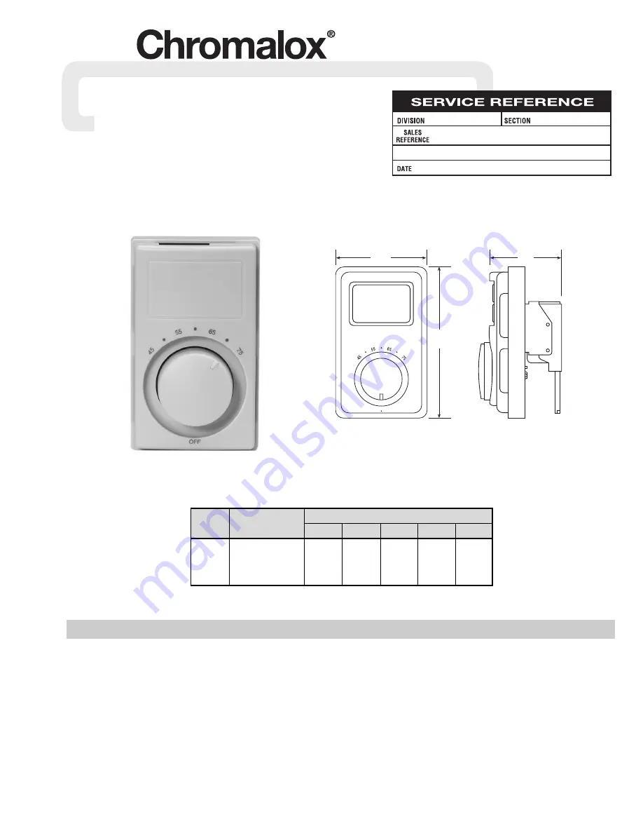
PK477
161-506096-001
JUNE, 1995
4WT
Installation Instructions
(Supersedes PK477)
Type WT Room Thermostat
© 2010 Chromalox, Inc.
GENERAL
Note:
Type WT thermostats are designed for temperature control
service only. Because they do not fail safe, they should not be used
for temperature limiting duty.
WARNING:
Users should install adequate back-up
controls and safety devices with their electric
heating equipment. Where the consequences of
failure may be severe, back-up controls are essen-
tial. Although the safety of the installation is the
responsibility of the user, Chromalox will be glad to
make equipment recommendations.
WARNING:
Not for use in hazardous environments
as described in the National Electrical Code.
Failure to comply can result in explosion or fire.
T
hermostat Location
1.
Mount in any standard electrical outlet box. Use of extra deep
box (3” x 2” x 3
1
/
2
”) makes for easier wiring.
2.
Locate outlet box about 5’ above floor on inside wall.
3.
Box location should be representative of the area to be con-
trolled. Avoid locations that are subject to drafts or false exter-
nal heat (such as solar radiation, direct heat from heaters, etc.).
Insure that the wall selected is capped to prevent drafts within
the wall.
Temp
Maximum Rating
Range
Contacts
Model
(°F)
128V AC
208V AC
240V AC
277V AC
Pilot Duty
125V AC
WT-121
45-75
SPST
22 amps
22 amps
22 amps
18 amps
(use with
or 2640
or 4575
or 5280
or 5000
AC
WT-122
45-75
DPST
total watts
total watts
total watts
total watts
contactor)
Specifications — Table A
4.72"
(110)
Front View
2.14"
(54)
Side View
2.86"
(73)


