Chromalox MicroTherm CMX Series Скачать руководство пользователя страница 11

9

Section 3 – Temperature Control Operations

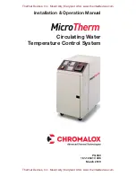
Figure 3.1 Control Panel Layout

Status and Diagnostic Indicators

System shuts down if any red diagnostic indicator is 
illuminated.

Low Water Pressure:
•  System water pressure is below 20 psi. 

(Disabled on CMX-180 models) 

Pump Overload:
•  Pump has drawn too much current.

Over Temperature:
•  System temperature has exceeded 260°F.

Most CMX units shipped from 1995 through 2018 will 
have been equipped with a Chromalox model 2104 
temperature controller. For these units, please refer-
ence the 2104 Quick Info Manual or Instruction Manual 
0037-75276 for complete technical details.

For specific controller Set-up Parameters, please refer 
Chromalox Manual PQ445-5

Most CMX units shipped from 2019 and onward will 
have been equipped with a Chromalox model 4081 
(standard controller) or 4082 (advanced controller).  For 
these units, please reference the 4081 & 4082 Quick 
Start Manual, Document PK531 (0037-75563) or In-
struction manual PK532-1 (0037-75562) for complete 
technical details.

Below is a list of the most common controller setups, 
with additional details available in Appendix C

CMX-250, Contactor – Dwg. 223-123625-053 


CMX-275, Contactor – Dwg. 223-123625-052

CMX-250, SCR – Dwg. 223-123625-055  


CMX-275, SCR – Dwg. 223-123625-058

CMX-250, Heat-Only – Dwg. 223-123625-057   
CMX-275, Heat-Only – Dwg. 223-123625-059

START/STOP Pushbuttons

Press 

START

 to start the 

pump.

Indicator will illuminate while
pump is running. Press 

STOP

 to stop the pump.

Temperature Control

Actual controller supplied may vary from picture.

Thermal Devices, Inc.  Mount Airy, Maryland USA   www.thermaldevices.com

Thermal Devices, Inc.  Mount Airy, Maryland USA   www.thermaldevices.com

Содержание MicroTherm CMX Series

Страница 1: ...ion Manual Circulating Water Temperature Control System PQ450 161 123417 036 March 2019 Thermal Devices Inc Mount Airy Maryland USA www thermaldevices com Thermal Devices Inc Mount Airy Maryland USA w...

Страница 2: ...11 Section 6 Maintenance 12 Section 7 Troubleshooting 17 Section 8 Speci cations 18 Appendix A CMX Closed Loop to Open Loop Cooling Conversion 19 Appendix B CMX Open Loop to Closed Loop Cooling Conve...

Страница 3: ...SME pressure relief valve that is factory set to 125 psi 150 psi with 7 5 hp motor A pressure switch ensures adequate water pressure in the system to help prevent pump cavitation and steam buildup on...

Страница 4: ...nt draw in the motor Long life mercury contactor switches heater power for millions of cycles and quiet trouble free operation Compact rugged cabinet fits into tight spaces Rolling casters allow easy...

Страница 5: ...plifying maintenance Figure 1 2 Control Panel Ordering Information Pump START STOP Pushbuttons Open Loop Cooling Model kW Volts Total Amperage CMX 250 4 4 5 240 13 6 CMX 250 4 4 5 480 6 8 CMX 250 9 9...

Страница 6: ...ot connect any valves or obstructions which could prevent free discharge from relief valve in a safe man ner Route line so water drains completely Do not allow drain to freeze or corrode shut Hydrauli...

Страница 7: ...nominal 3 8 Rear View Chromalox DRAIN COOLING OUTLET FROM PROCESS TO PROCESS 1 7 8 6 6 4 7 15 WATER SUPPLY COOLING INLET 12 5 16 28 1 2 Thermal Devices Inc Mount Airy Maryland USA www thermaldevices c...

Страница 8: ...drain Hydraulic Installation Closed Loop 1 Locate the unit as close as possible to the con trolled process in order to minimize pressure drops Make sure the unit is sitting on a solid level foundatio...

Страница 9: ...T WATER SUPPLY COOLING INLET FROM PROCESS TO PROCESS 1 7 8 6 6 4 7 15 12 5 16 28 1 2 Rear View Note Dimensions are nominal 3 8 S and TO PR Thermal Devices Inc Mount Airy Maryland USA www thermaldevice...

Страница 10: ...quipment Consult applicable codes for details 4 Pump Rotation Check With power off check the wiring connections by tugging on the lines Tighten all terminals in the control area These can loosen due t...

Страница 11: ...nd onward will have been equipped with a Chromalox model 4081 standard controller or 4082 advanced controller For these units please reference the 4081 4082 Quick Start Manual Document PK531 0037 7556...

Страница 12: ...lluminate 7 Once temperature has stabilized at the setpoint level review controllability of the system If the temperature is uctuating at an unacceptable level consult the temperature control instruct...

Страница 13: ...ect system power if the Pump Overload Indicator is illuminated Hazard of electric shock or elec trocution Disconnect all power and piping to the system After the system power is disconnected solve the...

Страница 14: ...power to the unit The controller will turn off 3 Turn off the water supply to the unit 4 Disconnect electrical supply to the unit 5 Carefully bleed pressure from the system by loos ening a pipe tting...

Страница 15: ...ove cable from the heater 8 Unbolt the heater 4 bolts and remove 9 Remove Bussing from old heater and re install on replacement heater using the same orientation 10 Replace heater and reverse procedur...

Страница 16: ...ocution Pump Motor Vent Line Heater Element Housing Motor Pump Housing Figure 6 3 Motor Vent Line Heat Exchanger Removal Replacement Closed loop system 1 Disconnect all power to the system 2 Bleed pre...

Страница 17: ...344 048419 004 4 Automatic Air vent 344 053181 001 5 Pressure Gauge 130 118661 021 6 Pressure Switch 292 121927 028 7 Pump Mechanical Seal 251 121946 019 8 Heat Exchanger Bundle Closed Loop 353 123367...

Страница 18: ...PAGE HEAT COOL OUT3 OUT4 F C AUX PV SP Chromalox CMX Series Temperature Control System HEATER CONTACTOR 1C 20 17 TRANSFORMER AUX CONTACT BLOCK 15 19 FUSE 1F CONNECT _____VOLT SUPPLY HERE MOTOR CONTAC...

Страница 19: ...ermine the problem and press pump reset button Over Temperature Indicator illuminated 1 System above temperature limit of 600 F 1 Allow unit to cool below 550 F and press reset on over temperature con...

Страница 20: ...sed cooling water ow Expanded Closed Loop Cooling 6 3 sq ft heat exchanger Solid State Power Control SCR heater switching Surge Reduction valve reduces water pressure spikes Door Interlock prevents op...

Страница 21: ...of the cooling con guration for both closed and open loop cooling These parts are located on the top of the cooling chamber Use pipe tape or other sealing compound when attaching threaded connections...

Страница 22: ...99 122818 003 3 1 4 NPT x 7 8 Nipple 1 piece 198 122817 002 4 1 2 NPT x 3 Nipple 1 piece 198 122817 090 5 1 2 NPT Street Elbow 1 piece 107 114567 005 6 Bush Reducer 1 2 x 1 4 NPT 2 pieces 032 121003 0...

Страница 23: ...AIN COOLING OUTLET OPEN LOOP Fig 2 Figure B4 Closed Loop Cooling CLOSED LOOP CLOSED LOOP WATER SUPPLY COOLING INLET FROM PROCESS TO PROCESS COOLING OUTLET Fig 1 Thermal Devices Inc Mount Airy Maryland...

Страница 24: ...4 NPT bush reducers 45 1 4 NPT x 7 8 nipple 39 compression tting 46 solenoid valve 43 removed earlier 8 Fig 1 Install 3 8 copper tubing 47 in compres sion tting 46 Route tubing to compression tting 4...

Страница 25: ...ower Limi 0 00 Primary Power Upper Limit 100 00 Secondary Power Lower Limit 0 00 Secondary Power Upper Limit 100 00 Sensor Break Off Set Point Lower Limit 32 F Set Point Upper Limit 250 F Set Point Ra...

Страница 26: ...Secondary Power Lower Limit 0 00 Secondary Power Upper Limit 100 00 Sensor Break Off Set Point Lower Limit 32 F Set Point Upper Limit 275 F Set Point Ramp Rate Off Main setpoint source Local Set point...

Страница 27: ...ondary Power Lower Limit 0 00 Secondary Power Upper Limit 100 00 Sensor Break Off Set Point Lower Limit 32 F Set Point Upper Limit 275 F Set Point Ramp Rate Off Main setpoint source Local Set point Al...

Страница 28: ...00 Secondary Power Lower Limit 0 00 Secondary Power Upper Limit 100 00 Sensor Break Off Set Point Lower Limit 32 F Set Point Upper Limit 275 F Set Point Ramp Rate Off Main setpoint source Local Set po...

Страница 29: ...ary Power Lower Limit 0 00 Secondary Power Upper Limit 100 00 Sensor Break Off Set Point Lower Limit 32 F Set Point Upper Limit 250 F Set Point Ramp Rate Off Main setpoint source Local Set point Alter...

Страница 30: ...i windup limit 100 Primary Cycle Time 30 0 s Secondary Cycle Time 10 0 s Primary Power Lower Limit 0 00 Primary Power Upper Limit 100 00 Secondary Power Lower Limit 0 00 Secondary Power Upper Limit 10...

Отзывы: