Chromalox MaxPac I Скачать руководство пользователя страница 21

- 20 -

© 2014 Chromalox

®

, Inc.

1-888-996-9258

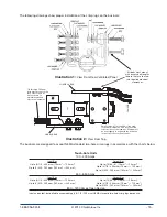
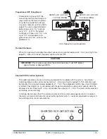
Shorted SCR Detection (optional), cont’d.

The latching and non-latching option is jumper selectable; the jumper is located on the plug-in 
shorted SCR detection board. Latching and non-latching operation by the output at J1 - 5 & 6 is 
controlled by J3 on the shorted SCR detection board 0135-28096.  When this jumper is installed, 
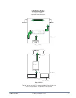
latching operation is achieved. The drawing below shows the Shorted SCR Detection board.

Heat Sink Over-Temperature

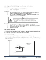
An external lamp or relay may be connected to J1 - 3 & 4 (see Fig. 2 on page 21) (this must be rated 
for the instrument power applied to J1 - 1 & 2). This will provide an indication to the operator that 

the heat sink is approaching an unsafe temperature level.  The unit will enter a shutdown mode if the 
temperature continues to rise.


UNIT SHIPPED IN NON-LATCHING MODE.

Содержание MaxPac I

Страница 1: ...PK480 2 P N 0037 75428 User s Manual www chromalox com 800 443 2640 2014 Chromalox Inc...

Страница 2: ...age Protection MOV Protection Built In Power Distribution Features for the MaxPac I II and III include Zero Crossover Firing Isolated Control Circuit On Off Control Inputs 120 thru 240 Vac 5 32 Vdc Dr...

Страница 3: ...g 8 4 2 Wiring 11 4 2 1 Touch Safe Design 11 4 2 2 Cover Removal and Installation 12 4 2 3 Power Load Wiring 12 4 2 4 Instrument Power 16 4 2 5 Grounding 16 4 2 6 Command Signal Wiring 17 4 2 7 Calibr...

Страница 4: ...reduce the risk of personal injury to persons from fire and electrical shock hazards Safety Alert Symbol International Shock Electrocution Symbol Each safety message is preceded by a safety alert symb...

Страница 5: ...d thermal shock The power SCR assemblies consist of one two or three pairs of SCRs connected back to back with an optional semiconductor fuse RC Snubber and MOV protection The firing circuit is based...

Страница 6: ...ich to mount your MaxPac please consider the following Temperature When mounting the SCR unit in a control panel attention should be paid to the enclosure tempera ture The SCR is rated to perform at i...

Страница 7: ...er of two directions The output power can only be connected from one direction The three mounting configurations are shown below MaxPac II Three Phase Two Leg Shown Open designs above 300 amps and all...

Страница 8: ...es of Proper Air Flow Pagoda Top Fan Air Louvers Louvers MaxPac Air Fan MaxPac Fan Enclosure Air Enclosure Fan Filter Forced Air In Forced Air Out Louvers Since hot air rises naturally it is not recom...

Страница 9: ...ctory 4 Installation Please read all information in this section before beginning the installation of your MaxPac Installation of the MaxPac requires three steps 1 Mounting 2 Power wiring 3 120 or 230...

Страница 10: ...mm 6 0 153mm 7 28 185mm FIRING PACKAGE FAN END 0 280 7 11mm 6 HOLES 7 2 183mm 0 0 0mm 1 3 33mm 7 3 185mm 13 3 337mm 14 6 371mm 12 0 305mm 13 3 338mm FIRING PACKAGE FAN END 0 280 7 11mm 6 HOLES 5 12 13...

Страница 11: ...8 11 7 298mm 0 0 0mm 1 3 33mm 9 3 237mm 13 31 338mm 14 62 371mm 21 4 543mm 22 4 568mm FIRING PACKAGE FAN END 3125 7 94mm 8 HOLES 5 3 135mm 5 8 148mm 0 0 0mm 1 3 33mm 11 3 28mm 16 3 414mm 17 6 448mm 9...

Страница 12: ...t installation wiring that is in accordance with the National Electrical Code and any local standards that may be applicable WARNING Hazardous Voltage Only qualified personnel should perform electrica...

Страница 13: ...Lift the cover from the base Install Wiring 3 Attach the wires to the bus bars in accordance with the instructions in the next section 4 Choose the entrance and exit directions for the wiring as desi...

Страница 14: ...L2 X1 X3 L2 Connection is NOT on MaxPac Four Wire 3 Leg Control MAX PAC III L1 L2 L3 X1 X2 X3 N N Connection is NOT on MaxPac IMPORTANT The I2 t fuses installed on the SCR are designed to protect the...

Страница 15: ...the SCR are designed to protect the SCR from faults on the load connection side They are NOT intended to provide wire protection CAUTION Three Wire 3 Leg Control MAX PAC III L1 L2 L3 X1 X2 X3 Single P...

Страница 16: ...side of the bus bar as shown to maintain required electrical clearances Illustration 2 View From Top Touch Safe Units 100 400 Amps Input Bus Up to 3 1 0 300 mcm 70 mm2 150 mm2 Up to 2 350 500 mcm 185...

Страница 17: ...the wire in the holes that maximize the distance for the wire to exit the enclosure This maximizes the distance from the cover to the non insulated connector When using the power distribution feature...

Страница 18: ...g 7 on page 21 1 5 Vdc Terminal J2 5 7 see Fig 5 on page 21 0 10 Vdc Terminal J2 10 7 see Fig 8 on page 21 4 20 mA Terminal J2 6 7 see Fig 6 on page 21 Auto Manual Input The MaxPac I II and III can be...

Страница 19: ...nal level compatible with the optional proportional firing board The plug in receptacle for the optional proportional board allows for an easy upgrade to proportional control The drive signal to the S...

Страница 20: ...stem An external indicating lamp or relay can be connected to J1 5 6 see Fig 2 on page 21 This indicator must be rated for the instrument power applied to J1 1 2 Three diagnostic LEDs show which SCR p...

Страница 21: ...rd 0135 28096 When this jumper is installed latching operation is achieved The drawing below shows the Shorted SCR Detection board Heat Sink Over Temperature An external lamp or relay may be connected...

Страница 22: ...L INPUT SIG 1 5 VDC PROPORTIONAL INPUT 4 5 2 3 1 J2 10 COMMON 7 8 9 6 5 J1 10 7 8 9 6 5 1 K J2 2 4 3 1 J2 2 4 3 1 J1 J3 120 230 INSTRUMENT POWER REQUIRED ON ALL CONFIGURATIONS 120 230 INSTRUMENT POWER...

Страница 23: ...are correctly applied Also make sure the Emergency Shutdown if used has N O contacts and jumper pins 4 5 on the 10 pin connector if remote manual bias are not used Please read the information on cali...

Страница 24: ...positive inputs to the MaxPac Power Pak EXAMPLE 0 5 mA input set to 0 mA input 4 20 mA input set to 4 mA input 7 With power off connect line voltage and load as shown 8 Connect meter to input and outp...

Страница 25: ...Voltage Output Indicator Output 100 mA Instrument Power Shorted SCR AC Voltage Output Indicator Output 100 mA Instrument Power MaxPac I II and III MaxPac IP Control Inputs Accepts all of the followin...

Страница 26: ...suffer corrosion Periodically check the power module for corrosion Damage Periodically check for rodent damage to wiring and other components Filters Many high powered control enclosures rely on blow...

Страница 27: ...oad If Demand Light is Off 1 Check incoming line power 2 Check the instrument power 3 Check the fuse on the main board 4 Verify the input signal 5 Check that remote shutdown J3 3 to 4 is open 6 Check...

Страница 28: ...ld 70mm2 0135 10008 LCD2 0 12 X 3 0 AWG or 2 0 Weld 95mm2 0135 10009 LCD3 0 12 X 4 0 AWG or 3 0 Weld 120mm2 0135 10010 LCD4 0 12 X 250 MCM or 4 0 Weld 150mm2 0135 10011 LCD250 12 X 300 MCM 150mm2 0135...

Страница 29: ...ained in accordance with Chromalox instructions Users are responsi ble for the suitability of the products to their application There is no warranty against damage resulting from corrosion misapplicat...

Страница 30: ...en Design 04 150 Amp Touch Safe Design 05 200 Amp Open Design 06 200 Amp Touch Safe Design 07 300 Amp Open Design 08 300 Amp Touch Safe Design 09 400 Amp Open Design 10 400 Amp Touch Safe Design 11 55...

Страница 31: ...tentiometer MXPC I 2 03 1 1 L1 F01 1 Typical Model Number Crimp Lug Chart Chromalox Panduit Conductor Size Torque In Lb Nm 0135 10002 LCD8 14A L 8 AWG 180 20 0135 10003 LCD6 14A L 6 AWG or 6 Weld 180...

Страница 32: ...mp Touch Safe Design 07 300 Amp Open Design 08 300 Amp Touch Safe Design 09 400 Amp Open Design 10 400 Amp Touch Safe Design 11 550 Amp Open Design 12 550 Amp Touch Safe Design 13 650 Amp Open Design...

Страница 33: ...otentiomete MXPC IP 2 03 1 1 L1 F01 1 Typical Model Number Crimp Lug Chart Chromalox Panduit Conductor Size Torque In Lb Nm 0135 10002 LCD8 14A L 8 AWG 180 20 0135 10003 LCD6 14A L 6 AWG or 6 Weld 180...

Страница 34: ...en Design 04 150 Amp Touch Safe Design 05 200 Amp Open Design 06 200 Amp Touch Safe Design 07 300 Amp Open Design 08 300 Amp Touch Safe Design 09 400 Amp Open Design 10 400 Amp Touch Safe Design 11 55...

Страница 35: ...equires Proportional Band MXPC II 2 03 1 1 L1 F01 1 Typical Model Number Crimp Lug Chart Chromalox Panduit Conductor Size Torque In Lb Nm 0135 10002 LCD8 14A L 8 AWG 180 20 0135 10003 LCD6 14A L 6 AWG...

Страница 36: ...uch Safe Design 05 200 Amp Open Design 06 200 Amp Touch Safe Design 07 300 Amp Open Design 08 300 Amp Touch Safe Design 09 400 Amp Open Design 10 400 Amp Touch Safe Design 11 550 Amp Open Design 12 55...

Страница 37: ...s Proportional Band MXPC III 2 04 1 1 L1 F02 1 Typical Model Number Crimp Lug Chart Chromalox Panduit Conductor Size Torque In Lb Nm 0135 10002 LCD8 14A L 8 AWG 180 20 0135 10003 LCD6 14A L 6 AWG or 6...

Страница 38: ...1000 6 4 2001 EN 55011 2007 Part 4 3 Contactors and 2 Conducted Disturbance Emissions Voltage motor starters EN 61000 6 4 2001 EN 55011 2007 AC semiconductor controllers and contactors for non motor l...

Страница 39: ...he Technical documentation required by Annex IV 3 of the Low Voltage Directive is maintained by Name of company and location in the European Union Year in which CE Marking was affixed 2002 Authorized...

Отзывы: