


- 17 -
© 2014 Chromalox
®
, Inc.
1-888-996-9258
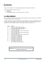
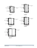
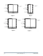
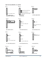
4.2.6 - Command Signal Wiring
Please refer to the figures on page 19 for illustrations of the 6-, 8-, and 10-pin input terminals.
MaxPac I, II, and III
On/Off Control Signals
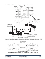
AC Input – The 120 thru 230 Vac signal lines are connected to terminal J1 - 7 & 8 (see Fig. 9 on page
21). An input voltage of 120 to 230 Vac turns the power On. The turn OFF voltage is 0 Vac.
DC Input – The 5 - 32 Vdc signal lines are connected to terminal J3 - 1 & 4 (see Fig. 10 on page 21).
An input voltage of 5 to 32 Vdc turns the power On. The turn OFF voltage is 0 Vdc.
Contact Closure Input – The dry contact signal lines are connected to terminal J3 - 1 & 2 (see Fig.
11 on page 21). A closed contact turns the power On. The turn OFF voltage is an open contact.
Process Analog Control Signals
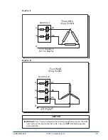
MaxPac I, II, and III have been factory calibrated. These units accept 0 - 5, 1 - 5, 0 - 10 Vdc, and 4 -
20 mA input signals that are connected to Terminal Block J2. The following signals are connected to:
0 - 5 Vdc: Terminal J2 - 9(+) & 7(-) (see Fig. 7 on page 21)
1 - 5 Vdc: Terminal J2 - 5(+) & 7(-) (see Fig. 5 on page 21)
0 - 10 Vdc: Terminal J2 - 10(+) & 7(-) (see Fig. 8 on page 21)
4 - 20 mA: Terminal J2 - 6(+) & 7(-) (see Fig. 6 on page 21)
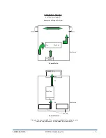
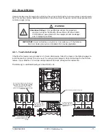
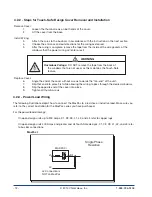
Auto/Manual Input
The MaxPac I, II, and III can
be wired to make it possible
to select an input from either a
temperature process controller
or a manual input potentiom-
eter. A switch is used to select
between the input from a 1K
potentiometer and a linear
control input (see Fig. 4 on page
21). The unit is shipped with a
jumper from terminals 2 and 3
of terminal block J2 (see illustra
-
tion 3). Remove jumper to install
auto/manual input.
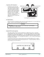
Demand Indicator
The LED demand indicator is located on the main PC board and is viewable through the cover. With
the On/Off control option, the indicator will display steady “on” and steady “off”. With the DOT Firing
option, the indicator will display the rapid firing sequence.
IMPORTANT: When enabling the Auto/Manual Input, the jumper from terminals 2
and 3 of terminal block J2 must be removed.
CAUTION
Illustration 3
NC
NO
CONTACT
NORMALLY CLOSED
(SWNC)
CONTACT
NORMALLY OPEN
(SWNO)
SWITCH
ASSEMBLY
(SW)
PANEL TO BE
MOUNTED TO
LEGEND
PLATE
(LP)
AUTO HAND
SWITCH KNOB
(SW)
AUTO
HAND
WIRING
1
4
NC NO
1K
POTENTIOMETER
CW
2
3