


- 12 -
© 2014 Chromalox
®
, Inc.
1-888-996-9258
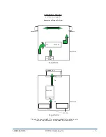
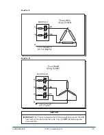
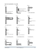
4.2.3 - Power/Load Wiring
The following illustrations depict how to connect the MaxPac to a resistive or inductive load. Make sure you
refer to the correct illustration for the MaxPac series you have purchased.
For the power/load drawings:
On open design units up to 300 Amps, X1, X2, X3, L1, L2, and L3 refer to copper lugs.
On open design units 400 Amps and greater and all Touch-Safe designs, X1, X2, X3, L1, L2, and L3 refer
to bus bar connections.
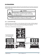
MaxPac I
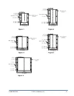
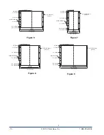
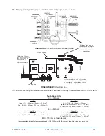
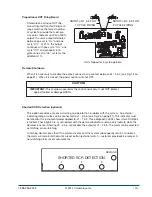
4.2.2 - Steps for Touch-Safe Design Cover Removal and Installation
Remove Cover:
1.
Loosen the thumb screws on both ends of the cover.
2.
Lift the cover from the base.
Install Wiring:
3.
Attach the wires to the bus bars in accordance with the instructions in the next section.
4.
Choose the entrance and exit directions for the wiring as desired.
5.
After the wiring is complete, remove the tape from the inside of the wire gaskets of the
windows that the power wiring will enter or exit.
Replace Cover:
6.
Angle the end of the cover without screws towards the “fan-end” of the unit.
7.
Slip that end into place first while allowing the wiring to pass through the desired windows.
8.
Slip the opposite end of the cover into place.
9.
Tighten all thumb screws.
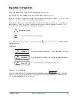
WARNING
Hazardous Voltage: DO NOT remove the tape from the back of
the windows that are not used, as this maintains the Touch-Safe
feature.
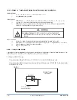
MAX PAC I
L2
L1
X1
Single Phase
Resistive
L2 Connection is
NOT on MaxPac