


5. Select the type network routing appropriate for your projector and select Enter.
Configuring the GPIO
The Generic Purpose Input Output (GPIO) provides a flexible method of interfacing with external
devices to the projector.
The GPIO is configured to automate real time events. Each of the seven pins is defined as either an
input or output depending on the required outcome. The remaining two pins are reserved for ground
and power.
Configure the pin as an input if you want the projector to respond to something the device does and
as an output if you want the external device to respond to an action taken by the projector. For
example, configure the pin as an output if you want the lighting in a room to automatically dim when
the projector is turned on.
This feature is only available on the web interface.
1. From the home page of the web interface, select MENU > Macros and GPIO.
2. Select GPIO Configuration.
3. In the GPIO Configuration dialog under Update the New Configuration, toggle the pins you
want active for the input and output.
A blue pin indicates input and a green pin indicates output.
4. Select Apply.
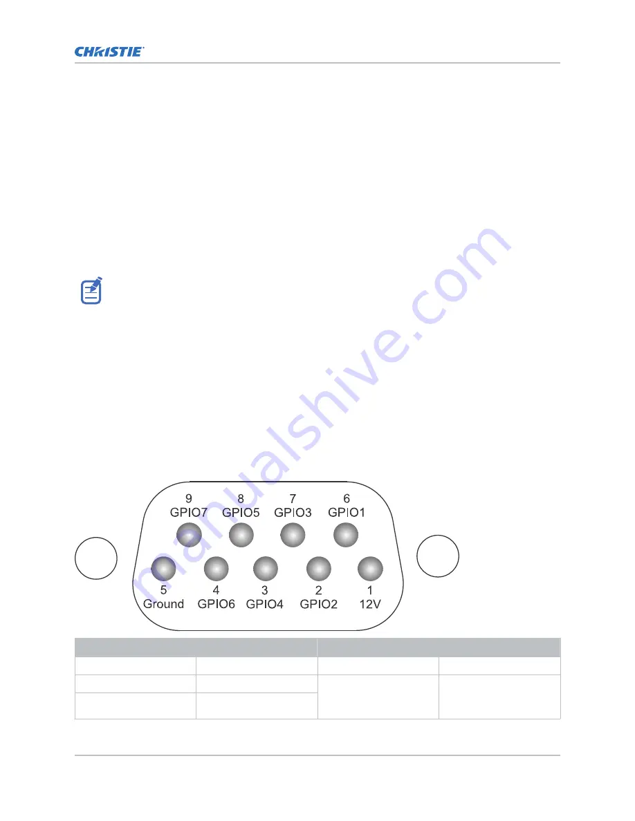
GPIO connector
The GPIO connector located on the input panel provides a flexible method of interfacing with the
projector. Seven GPIO pins are available on the nine pin D-Sub GPIO connector. Two other pins are
reserved for ground and power.
D-SUB pin number
Signal
Output high (Voh)
Notes
Pin 1
+12V
—
1A max
Pin 2
GPIO 2
5V
75mA max
(e)fused to prevent
damage
Pin 3
GPIO 4
Connecting devices and establishing communication
Griffyn 4K32-RGB Installation and Setup Guide
65
020-103314-05 Rev. 1 (04-2021)
Copyright
©
2021 Christie Digital Systems USA, Inc. All rights reserved.
Содержание TruLife+ Griffyn 4K32-RGB
Страница 1: ...Installation and Setup Guide 020 103314 05 Griffyn 4K32 RGB ...
Страница 77: ......


