background image

3-2

Solaria One/Solaria One

Service Manual

020-101039-02 Rev. 1 (06-2013)

Section 3: Parts and Module Replacement

3.2

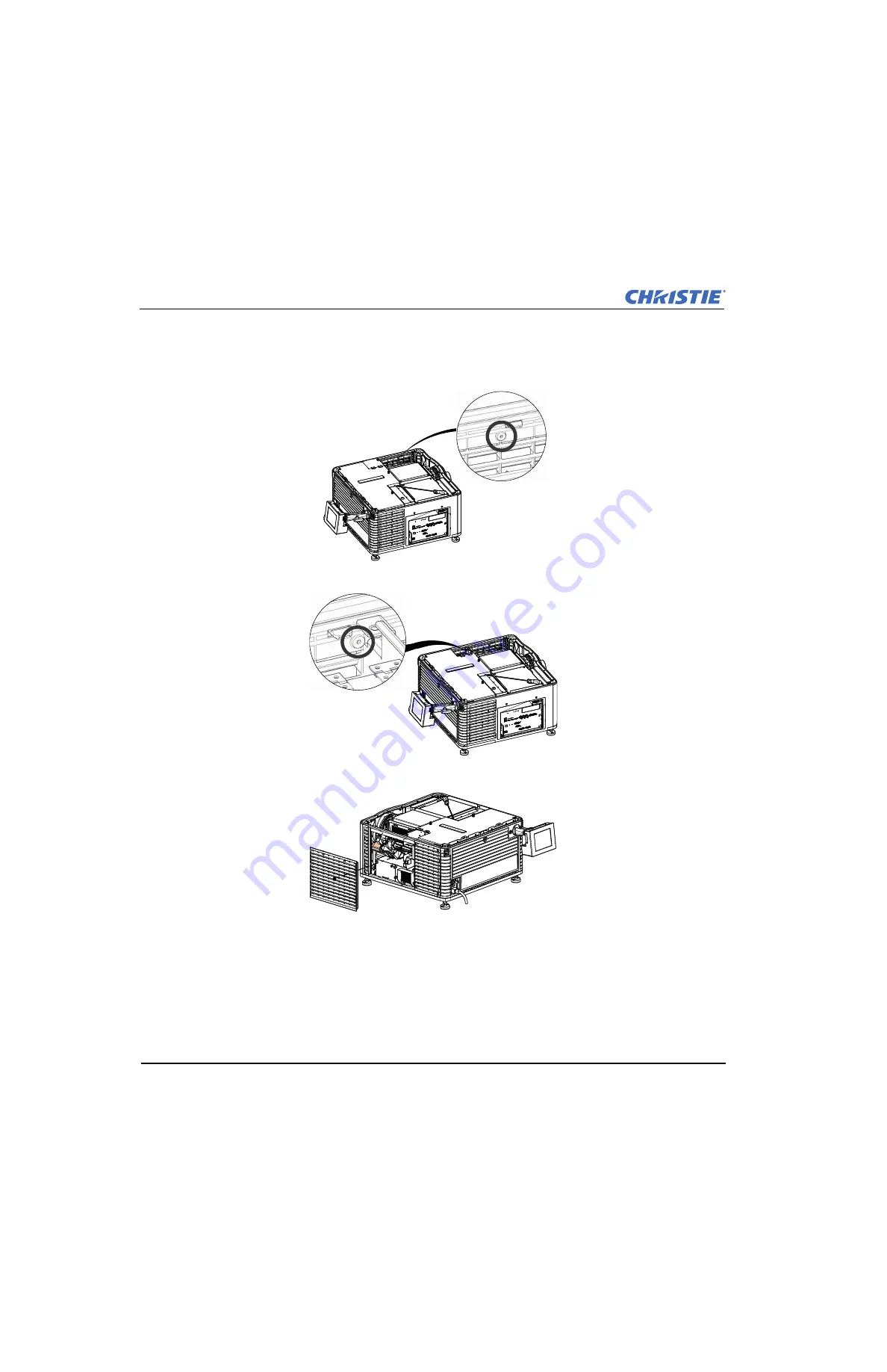
Inspect the Light Engine Compartment Filter

1. Remove the top lid.
2. Reach into the projector and then loosen the first service panel screw.

3. Open the integrator rod access door and loosen the second service panel screw.

4. Push the clips on the top of the service panel down and out to remove the service panel.

Содержание Solaria One

Страница 1: ...Solaria One Solaria One S e r v i c e M a n u a l 020 101039 02 ...

Страница 2: ......

Страница 3: ...Solaria One Solaria One S e r v i c e M a n u a l 020 101039 02 ...

Страница 4: ... high quality materials and components that can be recycled and reused This symbol means that electrical and electronic equipment at their end of life should be disposed of separately from regular waste Please dispose of the product appropriately and according to local regulations In the European Union there are separate collection systems for used electrical and electronic products Please help us...

Страница 5: ...n the Lamp 2 10 2 7 DMD Convergence 2 11 2 7 1 Preparation 2 11 2 7 2 Evaluate Convergence 2 11 2 7 3 Adjust Red Green Blue Formatter Convergence 2 13 2 7 4 Evaluate Convergence Adjustments 2 14 2 8 Manually Override the Shutter 2 14 3 Parts and Module Replacement 3 1 Inspect the Card Cage Filter 3 1 3 2 Inspect the Light Engine Compartment Filter 3 2 3 3 Clean a Washable Filter 3 3 3 4 Remove the...

Страница 6: ...e the Cardcage 3 25 3 30 2 Remove the Projector Intelligence Board 3 26 3 30 3 Remove the Projector Intelligence Faceplate Board 3 27 3 30 4 Remove the Integrated Cinema Processor 3 27 3 30 5 Remove the Christie IMB 3 28 3 30 6 Remove the Backplane 3 28 3 31 Fans 3 29 3 31 1 Remove the Anode Lamp Blower Fan 1 3 29 3 31 2 Remove the Cathode Lamp Blower Fan 2 3 30 3 31 3 Remove the Light Engine Fan ...

Страница 7: ...le Replacement Parts and Modules 6 1 Lamp and Filter Assemblies 6 1 6 2 Light Engine 6 1 6 3 Lamp Power Supply Igniter and Power Supplies 6 1 6 4 Optical Assemblies 6 1 6 5 PCB Assemblies 6 2 6 6 Fan Assemblies 6 2 6 7 Miscellaneous 6 2 6 8 Optional Accessories 6 3 6 9 Optional Lenses Solaria One 6 3 6 10 Optional Lenses Solaria One 6 3 7 Interconnections 7 1 Solaria One 7 1 7 2 Solaria One 7 2 8 ...

Страница 8: ......

Страница 9: ...etely 1 1 2 Lamp Only service technicians trained specifically by Christie on lamp replacement and lamp safety may handle the lamp The high pressure lamp may explode if improperly handled Always wear Christie approved protective safety clothing 598900 95 whenever the internal lamp door is open Failure to comply results in death or serious injury EXPLOSION HAZARD Lamp replacement must be performed ...

Страница 10: ...jury A dedicated earth wire must be installed on the projector before it can be connected to power The dedicated earth wire can only be installed by a Christie accredited service technician or an electrician All installations must meet the electrical codes for your area The protected earth wire must be green yellow 12 AWG minimum Failure to comply could result in death or serious injury Power rema...

Страница 11: ...ians trained specifically on lamp replacement and lamp safety may handle the lamp A high pressure lamp may explode if improperly handled Always wear Christie approved protective safety clothing 598900 95 whenever the lamp door is open or while handling the lamp Never attempt to access the lamp while it is running Wait at least 15 minutes after turning the lamp off before turning the projector off ...

Страница 12: ...h or serious injury You must keep all internal components clean during any service procedure In particular all of the projector optics must remain free of contaminants to perform at the level specified for the projector Even a small amount of dust or a fingerprint can degrade the image or cause a noticeable reduction of brightness When you service the projector take all necessary measures to avoid...

Страница 13: ...r the integrator module is moved or replaced its rotation must be corrected for proper focus and full illumination of the three digital micromirror devices DMDs 1 Display a full white field test pattern a On the touch panel controller TPC tap the Test Pattern icon in the task bar b Tap All Test Patterns c Tap RGB 12bit Full Screen White 2 Remove the top lid See Remove the Top Lid on page 3 4 3 Put...

Страница 14: ...rator rod set screws 10 Replace the top lid 2 2 Align the Fold Mirror If a corner or edge of an image is missing the fold mirror might be misaligned with the optical system To correct this issue 1 Remove the top lid and set it aside See Remove the Top Lid on page 3 4 2 Display a full white test pattern a On the touch panel controller TPC tap the Test Pattern icon in the task bar b Tap All Test Pat...

Страница 15: ...the boresight distance from the lens to the prism plane set by Christie For example when you move the top screw outward turn the bottom two boresight screws to maintain the overall distance Only adjust vertical boresight 1 8 of a turn or less at one time to maintain optimal lens performance i e factory setup of absolute lens distance to the prism It is critical that each turn of the cap screws is ...

Страница 16: ...th left and right horizontal adjustments according to the vertical adjustment 7 Check the image after each adjustment Continue to make adjustments until both top and bottom are equally sharp To make sure the lens is in the same relative position adjust the left and right horizontal adjusters in the opposite direction at the same time 8 When the top and bottom of the image are equally in focus lock...

Страница 17: ...equired 1 Remove the lens surround 2 Display the DC2K Framing test pattern a On the touch panel controller TPC tap the Test Pattern icon in the task bar b Tap All Test Patterns c Tap DC2K Framing 3 Loosen the right boresight set screw B 4 Turn the right boresight cap screw A 1 16 of a turn clockwise 5 Adjust the left boresight cap screw C equally in the opposite direction 6 If the quality of the p...

Страница 18: ...mediate vicinity must wear safety glasses with side shields Complete this procedure whenever the yellow notch filter is moved or replaced or when a new IOS Illumination Optics System is installed 1 Set up a spectroradiometer in front of the viewing screen and aim it at the center of the screen 2 Create an MCGD file a Tap Menu Advanced Setup MCGD File Setup b Tap Save As c Enter a name for the MCGD...

Страница 19: ... edit the lamp file settings Any changes made to the Lamp File set tings are applied to all channels that use this lamp file Field Description Measured Color The name of the Measured Color Gamut Data MCGD file you created in step 5 Target Color The Target Color Gamut Data TCGD value Select Color Verification Color Space The method of color decoding for the current source The default is YCbCr for a...

Страница 20: ...er number of frames that form one complete image Increase the display frame rate to reduce flicker from your source s L R Display Sequence Defines the frame order L R or R L required for 3D perspective This option only has meaning when the Frame Rate factor M is equal to 2 For this case 2 input frames of data are required to constitute a complete frame of image data This parameter tells the system...

Страница 21: ...filter cover Note Two different yellow notch filter assemblies are used in the Solaria One and Solaria One pro jectors version A and version B Version B allows greater adjustment of the yellow notch filter and a cut out holds the adjustment lever in position c Adjust the position of the yellow notch filter For version A loosen the set screw and then manually rotate the yellow notch filter Tighten ...

Страница 22: ...el suitable for your requirements 3 Tap Menu Advanced Setup Light Adjust 4 Record the number in the Intensity field 5 Tap Display Full Screen White Test Pattern 6 Complete a coarse lamp adjustment a Locate the Y axis adjustment label on the operator side of the projector b Insert a 5 mm hex driver A through the louvers at an angle below the Y axis adjustment label until it is firmly seated on the ...

Страница 23: ...ce adjustment 2 7 1 Preparation Reset the red green and blue digital micromirror device DMD values to their default settings Tap Menu Service Setup Digital Convergence Default Make sure the projected image is centered and focused on the screen If it is not a boresight alignment might be required See Adjust Vertical Boresight Angle on page 2 3 Make sure the primary lens is installed Configure the p...

Страница 24: ...e is higher than both Green and Red 2 Center Shows that Blue is high and to the left and Red is twisted 3 Right Note Blue to the left Yellow to the right and White in the middle This shows that Blue is separated from Green to the left Compare to the left where Magenta is to the top on the right Red is on the bottom to the left This is evidence of counter clockwise twist in Red and that Blue is hig...

Страница 25: ...the adjustment functions are the same The vertical and twist adjustments work together on the horizontal axis The physical layout of the Formatter boards determines the behavior of the Twist and Vertical adjustments The vertical adjustment screw and twist adjustment screw interact with each other such that if one is turned in the opposite direction of the other the twist is affected If both screws...

Страница 26: ...ter area should be perfectly aligned and display solid white pixels The Red should be evenly 1 4 to 1 2 a pixel out all the way around the outer area and display cyan green blue toward the center of the screen Green and Blue should always be perfectly aligned to each other to within pixel total in one or a combina tion of directions 2 8 Manually Override the Shutter Use this procedure to override ...

Страница 27: ...Solaria One Solaria One Service Manual 2 15 020 101039 02 Rev 1 06 2013 5 Manually open or close the shutter 6 Replace the high security lid and the top lid 7 Replace the lens 8 Reconnect the projector to AC power and turn it on ...

Страница 28: ......

Страница 29: ... if you are operating the projector in a dusty or dirty environment The filter is located on the left side of the projector behind the air filter cover 1 Loosen the 2 captive screws on the bottom of the filter cover 2 Pull the cover out and down 3 Slide the air filter out and inspect it If the filter appears dirty and you cannot see through it replace it with a new paper filter or clean it if it i...

Страница 30: ...3 2 Inspect the Light Engine Compartment Filter 1 Remove the top lid 2 Reach into the projector and then loosen the first service panel screw 3 Open the integrator rod access door and loosen the second service panel screw 4 Push the clips on the top of the service panel down and out to remove the service panel ...

Страница 31: ...1 Hold the filter on an angle under warm running water so the water flows through the filter in the opposite direction of the air flow indicator on the side of the filter 2 Rinse the filter thoroughly 3 Submerge the filter for a minimum of 30 minutes in a container of warm water and two tablespoons of mild detergent or liquid dish soap If the filter is extremely dirty move the filter from side to ...

Страница 32: ...e projector off and then disconnect it from AC power 3 Remove the top lid See Remove the Top Lid on page 3 4 4 Remove the cardcage intake air filter cover See Inspect the Card Cage Filter on page 3 1 5 Remove the lens surround 6 Remove the 4 screws that secure the skin to the projector structure 7 On a Solaria One projector remove the set screws from the horizontal and vertical lens adjustment kno...

Страница 33: ... securing the ball mount to the projector and then remove the ball mount 3 7 Remove the High Security and Light Engine Lid 1 Turn the lamp off and cool the projector for at least 15 minutes 2 Turn the projector off and then disconnect it from AC power 3 Remove the top lid See Remove the Top Lid on page 3 4 4 Unlock the high security A lid with the high security key 5 Lift the lid up and out 6 Remo...

Страница 34: ...he red and black leads from the switch 6 Remove the two nuts securing the switch to the frame and then remove the interlock switch 3 9 Remove the Cardcage Skin This cardcage skin should never need to be removed unless it is damaged and requires replacement From the rear of the projector the cardcage skin is on the right side of the projector 1 Turn the lamp off and cool the projector for at least ...

Страница 35: ...ove the Rear Skin The rear access frame interlocks with the side skins 1 Turn the lamp off and cool the projector for at least 15 minutes 2 Turn the projector off and then disconnect it from AC power 3 Remove the top lid See Remove the Top Lid on page 3 4 4 Remove the touch panel controller TPC See Remove the Touch Panel Controller on page 3 5 5 Remove the safety shield See Remove the Safety Shiel...

Страница 36: ... lug 10 Open the lamp door 11 Loosen the 5 top skin screws 12 Pull the skin forward and out 3 11 Remove the Service Door The side skin service door allows access to the Low Voltage Power Supply LVPS integrator fold mirror and light engine air filter 1 Turn the lamp off and cool the projector for at least 15 minutes 2 Turn the projector off and then disconnect it from AC power 3 Remove the top lid ...

Страница 37: ...1 Turn the lamp off and cool the projector for at least 15 minutes 2 Turn the projector off and then disconnect it from AC power 3 Remove the top lid See Remove the Top Lid on page 3 4 4 Remove the service door See Remove the Service Door on page 3 8 5 Loosen the 3 screws from the bottom of the exhaust panel skin 6 Remove the top 4 hex screws 7 Pull the skin forward and out 3 13 Remove the Safety ...

Страница 38: ...safety clothing including a full face shield Kevlar gloves and a ballistic nylon jacket 4 Never attempt to remove the lamp when it is hot The lamp is under pressure when hot and may explode causing personal injury death or property damage Allow the lamp to cool completely before replacing it Improper installation of the lamp can damage the projector 3 14 1 Remove the Existing Lamp 1 Turn the lamp ...

Страница 39: ...etized ball driver 8 For CDXL 14 or CDXL 16 lamps a Loosen the extension nut screw 1 b Hold the cathode end of the lamp with your right hand and the anode end with your left hand and care fully turn the lamp with your right hand so that it unthreads from the extension nut Make sure the lamp does not contact the reflector or the UV filter c With your left hand guide the cathode end of the lamp out ...

Страница 40: ...protective case and then place the lamp within the case on the floor where it cannot fall or be bumped WARNING Handle the protective case with extreme caution the lamp is hazardous even when packaged Dispose of lamp box according to local area safety regulations 11 Install the new lamp See Install the New Lamp on page 3 12 3 14 2 Install the New Lamp Handle the lamp by the cathode anode end shafts...

Страница 41: ...ghten the extension nut screw f Move to step 7 6 For the CDXL 21S1 lamp a Hold the anode end of the new lamp in your left hand and angle it up through the hole in the back of the reflector assembly Insert your right index and middle finger through the back of the reflector and guide the lamp onto the cathode clamp Be careful not to hit the lamp against the reflector b Thread on and hand tighten th...

Страница 42: ...g a hex key 7 Pull the lens out of the lens mount and then install a small lens cap on the rear of the lens 8 Remove the small rear cap from the new lens Keep the front cap on 9 Align the tabs on the lens plate with the lens mount Insert the lens until it connects with the magnets on the mount When the lens contacts the magnetic plates it is seated correctly 10 Secure the lens clamp by rotating it...

Страница 43: ...ety Shield on page 3 9 6 Remove the 2 screws from the top firewall bracket and then remove the bracket 7 Remove the 2 screws holding the firewall to the cathode blower assembly 8 Disconnect the fan1 harness from the firewall 9 Lift the firewall up and out of the top of the projector 3 17 Replace the Standby Power Supply The standby power supply is installed next to the low voltage power supply LVP...

Страница 44: ...isconnect the standby power supply inline connector behind the card cage 11 Loosen the 2 captive screws on the cap plate and then remove it 12 Pull the standby power supply harness out of the projector through the cap plate opening 13 Remove the clip holding the stand by wire to the LVPS 14 Remove the two screws from the standby power supply bracket and then remove the bracket and set it aside 15 ...

Страница 45: ... to the mounting plate 11 Remove the screw securing the cable clamp 12 Remove the clip securing the standby cable to the LVPS 3 19 Remove the Projector Feet 1 Turn the lamp off and cool the projector for at least 15 minutes 2 Turn the projector off and then disconnect it from AC power 3 Prop up the appropriate end of the projector or shift the projector off of the table or pedestal to create enoug...

Страница 46: ...e Remove the Rear Skin on page 3 7 5 Remove the anode blower firewall See Remove the Anode Lamp Firewall on page 3 15 6 Remove the cathode lamp blower See Remove the Cathode Lamp Blower Fan 2 on page 3 30 7 Remove the reflector assembly See Remove the Reflector Assembly on page 3 19 8 Remove the lamp adjust assembly See Remove the Lamp Adjust Assembly on page 3 18 9 Remove the 3 screws securing th...

Страница 47: ...el Controller on page 3 5 6 Remove the anode blower and firewall See Remove the Anode Lamp Firewall on page 3 15 7 Remove the 2 screws securing the lamp over temperature sensor 8 Remove the 2 P clips from the lamp over temperature sensor bracket and push the bracket aside 9 Remove the 4 screws that secure the reflector module Three of these screws are located on the bracket outside the reflector T...

Страница 48: ...3 25 Replace the Light Engine Wear gloves and an electro static bracelet when working with the light engine The light engine can be removed as an assembly with the harnesses still attached Removing the light engine this way reduces the risk of damage to other projector components 1 Turn the lamp off and cool the projector for at least 15 minutes 2 Turn the projector off and then disconnect it from...

Страница 49: ...and then lift the light dump up and out of the projec tor 9 Disconnect the LVDS cables from the backplane a Press both latches on the sides of the cable connector with equal pressure b Pull the cable connector outward with even pressure Do not use a twisting motion to disconnect the cable connector Note When replacing the LVDS cables the This Side Up label on the connector must face outward Twisti...

Страница 50: ...ve cover 3 26 Replace the Douser Assembly The douser is attached to the light engine prism It can be removed on its own or with the light engine 1 Turn the lamp off and cool the projector for at least 15 minutes 2 Turn the projector off and then disconnect it from AC power 3 Remove the top lid See Remove the Top Lid on page 3 4 4 Remove the high security lid See Remove the High Security and Light ...

Страница 51: ...h the top of the projector 3 28 Remove the Lens Mount 1 Turn the lamp off and cool the projector for at least 15 minutes 2 Turn the projector off and then disconnect it from AC power 3 Remove the lens surround 4 Remove the lens See Remove the Lens on page 3 14 5 Remove the top lid See Remove the Top Lid on page 3 4 6 Remove the front skin See Remove the Front Skin on page 3 4 7 Remove the plate be...

Страница 52: ...ed to select between the 110V and 220V power source 3 29 1 110V AC Line Filter 1 Turn the lamp off and cool the projector for at least 15 minutes 2 Turn the projector off and then disconnect it from AC power 3 Remove the lamp See Remove the Existing Lamp on page 3 10 4 Remove the side and rear projector skins See Remove the Exhaust Panel Skin on page 3 9 and Remove the Rear Skin on page 3 7 5 Remo...

Страница 53: ...IMB and backplane Note When replacing the cardcage you must replace the anti tamper label on the side of the cardcage 1 Turn the lamp off and cool the projector for at least 15 minutes 2 Turn the projector off and then disconnect it from AC power 3 Remove the top lid See Remove the Top Lid on page 3 4 4 Remove the high security lid See Remove the High Security and Light Engine Lid on page 3 5 5 Re...

Страница 54: ... well as component swapping between projectors When boards are replaced the system stores a copy of the latest software version on the projector so that it can be selected through the TPC and updated Note When replacing the projector intelligence board you must replace the anti tamper label on the side of the cardcage 1 Turn the lamp off and cool the projector for at least 15 minutes 2 Turn the pr...

Страница 55: ... faceplate board When reinstalling the PIBS1 and PIBS1 faceplate board you must perform Marriage so you can continue to play encrypted content See Activate Marriage in the Solaria One or Solaria One user manuals 3 30 4 Remove the Integrated Cinema Processor The ICP is located in the cardcage on the operator side of the projector The ICP is the image processing electronics for incoming video signal...

Страница 56: ...istie IMB 8 Remove the 2 screws securing the Christie IMB to the faceplate When reinstalling the Christie IMB you must perform Marriage so you can continue to play encrypted con tent See Activate Marriage in the Solaria One or Solaria One user manuals 3 30 6 Remove the Backplane The backplane is located at the back of the cardcage The PIBS1 IMB and ICP board are connected directly to the backplane...

Страница 57: ...safety clothing and a face shield when performing service with the service safety shield removed and a lamp installed The anode lamp blower is located at the rear of the projector behind the lamp access door 1 Turn the lamp off and cool the projector for at least 15 minutes 2 Turn the projector off and then disconnect it from AC power 3 Put on your protective clothing and face shield and then unlo...

Страница 58: ...door Note When replacing the cathode lamp blower you must replace the anti tamper label on the side of the lamp blower assembly 1 Turn the lamp off and cool the projector for at least 15 minutes 2 Turn the projector off and then disconnect it from AC power 3 Remove the anode blower firewall See Remove the Anode Lamp Firewall on page 3 15 4 Remove the 3 screws holding the lamp adjust cable plate to...

Страница 59: ...amp off and cool the projector for at least 15 minutes 2 Turn the projector off and then disconnect it from AC power 3 Remove the top lid See Remove the Top Lid on page 3 4 4 Pull the cardcage outward to access the fan connectors See Remove the Cardcage on page 3 25 5 Remove the service door See Remove the Service Door on page 3 8 6 Loosen the 2 captive screws securing the filter access door and t...

Страница 60: ...connect it from AC power 3 Remove the top lid See Remove the Top Lid on page 3 4 4 Remove the cardcage air intake filter cover and filter See Inspect the Card Cage Filter on page 3 1 5 Remove the front skin See Remove the Front Skin on page 3 4 6 Remove the high security lid See Remove the High Security and Light Engine Lid on page 3 5 7 Disconnect the four inline connectors from the fan power har...

Страница 61: ... firewall cutout that separates the lamp housing from the light engine 1 Turn the lamp off and cool the projector for at least 15 minutes 2 Turn the projector off and then disconnect it from AC power 3 Remove the top lid See Remove the Top Lid on page 3 4 4 Remove the service door See Remove the Service Door on page 3 8 5 Remove the 6 integrator housing screws 6 Remove the housing 7 Remove the 2 r...

Страница 62: ...ed to sample the light coming through the fold mirror 1 Turn the lamp off and cool the projector for at least 15 minutes 2 Turn the projector off and then disconnect it from AC power 3 Remove the top lid See Remove the Top Lid on page 3 4 4 Remove the front skin See Remove the Front Skin on page 3 4 5 Disconnect the harness from the light sensor module 6 Remove the 2 screws that secure the sensor ...

Страница 63: ...rojector off and then disconnect it from AC power 3 Remove the lamp See Replace the Lamp on page 3 10 4 Remove the side projector skin See Remove the Exhaust Panel Skin on page 3 9 5 Remove the 4 cold mirror heat sink plate screws and then remove the heat sink A 6 Remove the top 2 hex screws and clips holding the cold mirror 7 Loosen the bottom 2 hex screws holding the cold mirror 8 Grasp the top ...

Страница 64: ...sconnect it from AC power 3 Remove the top lid See Remove the Top Lid on page 3 4 4 Remove the side skin See Remove the Exhaust Panel Skin on page 3 9 5 Remove the contrast aperture See Remove the Contrast Aperture on page 3 33 6 Remove the light sensor module and move it aside See Remove the Light Sensor Module on page 3 34 7 Loosen the 2 5mm locking hex screw and remove the 2 2 5mm hex screws th...

Страница 65: ...6 Remove the Illumination Optic System UV HAZARD Always wear protective safety clothing and a face shield when perform ing service with the safety shield removed and a lamp installed The IOS is a magnesium frame that holds the light engine The light tube and most optical components are fastened to the IOS All components except the second fold mirror can be removed on their own therefore the need t...

Страница 66: ...of the IOS 11 Lift the light engine enclosure and the IOS out of the projector housing When reinstalling the IOS you must complete these tasks a Adjust the aperture shadows b Reshoot the MCGD c Verify the TCGD correction d Create new screen files e Verify the brightness uniformity 12 Remove the 4 screws securing the IOS to the light engine enclosure ...

Страница 67: ...ministrator Setup Upgrade 2 Tap an upgrade file in the Available Upgrade Files list 3 Tap Remove 4 3 Install an Upgrade You need Administrator or Service permissions to complete this procedure 1 Tap Menu Administrator Setup Upgrade 2 Tap an upgrade file in the Available Upgrade Files list 3 Tap Next 4 Tap a component in the Component list 5 Select one of these options 6 Tap Next Option Description...

Страница 68: ... upgrade file in the Folder list 5 Tap the upgrade file and then tap Open 6 Select the type of file to restore in the Select type list 7 Tap Restore 8 Tap Yes 4 6 Restore Factory Default Settings You need Service permissions to complete this procedure You can restore configuration preference channel and user files 1 Tap Menu Service Setup File Management 2 Select a file type to restore in the Sele...

Страница 69: ...nual 4 3 020 101039 02 Rev 1 06 2013 4 8 Delete Projector Files You need Service permissions to complete this procedure 1 Tap Menu Service Setup File Maintenance 2 Select a file type in the File Type list 3 Tap and drag a file from the Projector Files pane to the trash can icon 4 Tap Yes ...

Страница 70: ......

Страница 71: ...hristie support If the TPC is connected to the projector and the LEDs on the input panel are illuminated on the TPC verify in the Operational Status region of the Main panel does not indicate a PIBS1 failure Touch Panel Controller Make sure the TPC is connected to the projector If the TPC fails to initialize make sure the compact flash on the left side is installed correctly If the TPC fails to in...

Страница 72: ... filters are not blocked Listen for a clicking noise that indicates the ballast is attempting to strike the lamp If you do not hear a click ing noise there might be a problem with the ballast Contact a Christie accredited service technician to resolve the issue If you hear a brief clicking noise but the lamp does not ignite replace the lamp Lamp Suddenly Turns Off Tap Menu Advanced Setup Lamp Powe...

Страница 73: ...perate reliably at a lower power setting Fold mirror misalignment Contact your Christie accredited service technician to resolve the issue Integrator rod misalignment Contact your Christie accredited service technician to resolve the issue Blank Screen No Display of Cinema Image Ensure the lens cap is not on either end of the lens Ensure the lamp is ON Confirm all power connections are still OK En...

Страница 74: ...ected properly Check the cable connections and make sure the alternative source is selected Verify you can select test patterns If you can check your source connections again The Display is Jittery or Unstable Verify that the input device is connected properly If the input device is not connected properly the projector repeatedly attempts to display an image The horizontal or vertical scan frequen...

Страница 75: ...020 101039 02 Rev 1 06 2013 5 4 Christie IMB For troubleshooting information see the Christie Integrated Media Block User manual available for download on the Christie web site http www christiedigital com en us products accessories Pages Christie IMB 011 103895 XX aspx ...

Страница 76: ......

Страница 77: ...04655 xx Lamp CDXL 14M 1 4 kW Xenon 003 003066 xx Lamp CDXL 16M 1 6 kW Xenon 003 003900 xx Lamp CDXL 21S1 2 1 kW Xenon 003 004258 xx Light Engine Blower Assembly 003 110862 xx Part Name Description Christie Service Kit Part Harness Kit LVDS SFB to CBP 003 111832 xx Light Engine Assembly 003 102958 xx Part Name Description Christie Service Kit Part Lamp Power Supply LPS 003 120704 xx Low Voltage Po...

Страница 78: ...AC Line Filter 20A 003 004456 xx ASSY Knob LM Plastic Horizontal Solaria One 003 004462 xx ASSY Knob LM Plastic Vertical Solaria One 003 004463 xx ASSY Temperature Sensor 003 100618 xx Feet 4x adjustable front feet 120mm and back feet 203mm 003 002146 xx Flexible Shaft X Lamp Adjust 003 103248 xx Flexible Shaft Y Lamp Adjust 003 103249 xx Flexible Shaft Z Lamp Adjust 003 103250 xx Interlock Switch...

Страница 79: ...cket face 598900 095 Rack Stand Full 108 416102 xx Dual Polarizer Frame Kit 108 462103 xx Part Name Description Christie Service Kit Part 1 2 1 72 69 DLPCine Zoom Lens 108 458108 xx 1 33 2 1 69 DLPCine Zoom Lens 108 459109 xx 1 62 2 7 69 DLPCine Zoom Lens 108 460101 xx 2 09 3 9 69 DLPCine Zoom Lens 108 461102 xx Part Name Description Christie Service Kit Part 1 2 1 7 69 DLPCine Zoom Lens 108 46410...

Страница 80: ......

Страница 81: ...6 7 0 HIW 0 5LJKW 5HFHSWDFOH Z LOWHU RQO 5HFHSWDFOH Z LOWHU DUWK RQQHFWLRQ XJ 6WDQGE 6XSSO 9 1HXWUDO 1 LQH 0 0 RXVHU 63 RXQGDU 3 8 DQ DQ DQ DQ 0DLQ 3RZHU 73 LVFRQQHFW 3 HDOWK 0 HDOWK 3 6 HDOWK 0 LUH ODUP 836 QSXW 9 RWWRP DQ 936 ZLWK XLOW LQ DQ KULVWLH QWHJUDWHG 0HGLD ORFN 1 6 1 6 3 6 6 QF 6 VWHP 5HVHW PHUJHQF 6WDUW 0DUULDJH HQ RFN OO 7HPSHUDWXUH 6HQVRUV 3 H 3 H 3 H 3 H 3 H 3 H 6 QF2XW H6 7 H6 7 QJ...

Страница 82: ...3 RXQGDU 3 8 DQ DQ DQ DQ 0DLQ 3RZHU 73 LVFRQQHFW 3 HDOWK 0 HDOWK 3 6 HDOWK 0 LUH ODUP 836 QSXW 9 RWWRP DQ 936 ZLWK X LOW LQ DQ KULVWLH QWHJUDWHG 0HGLD ORFN 1 6 1 6 3 6 6 QF 6 VWHP 5HVHW PHUJHQF 6WDUW 0DUULDJH HQ RFN OO 7HPSHUDWXUH 6HQVRUV 3 H 3 H 3 H 3 H 3 H 3 H 6 QF2XW H6 7 H6 7 QJHVW 7 2XW 63 6HFXULW LG 7DPSHU 6ZLWFK 6HFRQGDU 3RZHU DWKRGH ORZHU DQ 0DLQ QSXW 9 3 6 5 6 6 3 0 5HVHW 56 3 6 DUWK URXQ...

Страница 83: ...TE The horizontal and vertical lens adjustment knobs on the Solaria One projector are not illustrated To remove the front skin you must first remove these knobs LABEL DESCRIPTION 1 Top Lid 2 Cardcage Panel Skin 3 Front Face Skin 4 Air Filter Cover 5 Lens Surround 6 Exhaust Panel Skin 7 Service Door 8 Rear Lamp Door 9 touch panel controller TPC 1 2 3 4 5 6 7 8 9 ...

Страница 84: ...IMB PIBS1 and PIBS1 faceplate 8 Ballast 15 Power Supply Tray 2 Backplane 9 Reflector 16 Lens Mount 3 Cardcage 10 Lamp Temperature Sensor 17 Douser Assembly 4 Light Engine Cover 11 Lamp Cover 18 Light Engine 5 High Security Lid 12 Lamp 19 Card Cage Fan Pack Assembly 6 Safety Shield 13 AC Line Filters 7 Cathode Blower Assembly 14 IOS Assembly 1 2 3 5 6 7 8 9 10 11 12 13 14 15 16 17 18 19 20 4 ...

Страница 85: ...S1 and PIBS1 faceplate board 8 Cathode Blower Assembly 15 IOS Assembly 2 Backplane 9 Ballast 16 Power Supply Tray 3 Cardcage 10 Reflector 17 Lens Mount 4 IMCB 11 Lamp Temperature Sensor 18 Douser Assembly 5 Light Engine Cover 12 Lamp Cover 19 Light Engine 6 High Security Lid 13 Lamp 20 Card Cage Fan Pack Assembly 7 Safety Shield 14 AC Line Filters 1 2 3 5 6 7 8 9 10 11 12 13 14 15 16 17 18 19 20 4...

Страница 86: ...39 02 Rev 1 06 2013 8 4 Light Path LABEL DESCRIPTION 1 Reflector 2 Lamp 3 UV Filter 4 Cold Mirror 5 Integrator Rod 6 Lens 1 7 Fold Mirror 1 8 Lens 2 9 Yellow Notch Filter 10 Lens 3 11 Lens 4 12 Fold Mirror 2 13 Lens 5 14 Light Engine 15 Lens 1 2 3 4 5 6 7 8 9 10 11 12 13 14 15 ...

Страница 87: ......

Страница 88: ...s ph 714 236 8610 Canada Kitchener ph 519 744 8005 United Kingdom ph 44 118 977 8000 France ph 33 0 1 41 21 00 36 Germany ph 49 2161 664540 Eastern Europe ph 36 0 1 47 48 100 Middle East ph 971 0 4 299 7575 Spain ph 34 91 633 9990 Singapore ph 65 6877 8737 Beijing ph 86 10 6561 0240 Shanghai ph 86 21 6278 7708 Corporate offices Worldwide offices ...

Отзывы: