Chapter
6Useful Utilization (Optional)
62
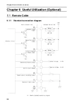
6.1.2
Pin Assignments
Wire color
Pin #
Signal name
Description
Black
①
Operation input
signal
*1
Remote
signals
(Input)
With
④
and
⑧
short-circuited,
①
is short-
circuited to start operation.
Red/white
④
Remote control
switching signal
*1
④
and
⑧
are short-circuited to start remote
operation.
Once this short circuit is established, ordinary
operation via the AT3 panel is disabled.
Yellow
⑦
Ability level change
*2
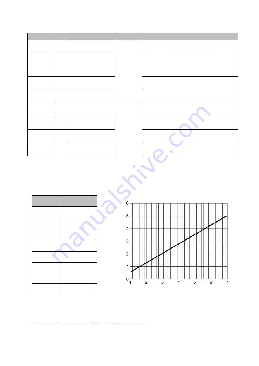
Voltage (0 to 5 V) can be applied between
⑦
and
⑧
to change suction power levels.
Yellow/white
⑧
GND
―
Black/white
②
Operating pressure
signal
Output
signals
Outputs the current operating pressure.
Analog signal: 1 to 5 V; impedance
4.7 kΩ
Red
③
Filter clogging output
signal
*3
Outputs HI during operation and LO when
clogging occurs.
Green
⑤
Operation output
signal
*3
Outputs LO during operation and HI when
stopped.
Green/white
⑥
Abnormal output
signal
*3
Outputs HI during operation and LO when an
error occurs.
【
Filter clogging output signal
】
Pin
③
:
When WARN2, WARN4 or WARN5 occurred
【
Abnormal output signal
】
Pin
⑥
:
When any ERR occurred
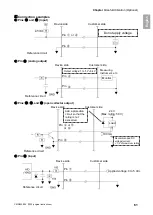
*1: Contact input (non-voltage contact)
*2: Analog input (0 to 5 V)
Do not apply more than +5.0 V.
【
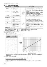
Threshold table for voltage applied to pin
⑦
】
Suction
power level
Voltage (Vdc)
1
0.6 to 1.1
2
1.2 to 1.7
3
1.8 to 2.3
4
2.4 to 2.9
5
3.0 to 3.5
6
3.6 to 4.1
7
4.2 to 5.0
Allow for an error of
4% when setting voltage. Specifically, apply the midpoint of the voltage range
for each level.
*3: Open collector output
:
NPN
The maximum absolute rating is 50 V for voltage and 100 mA for current.
The recommended value is half or less of the rating.
In case of adding an inductor (e.g., relay), install a noise limiter (approx. 33 Ω + 0.1 μF), diode, or
the like.
Voltage
(Vdc)
Suction power level
Содержание CBA-1500AT3-HC-DSA-V1
Страница 5: ...1 CMN023 005 Translation of the original instructions 3 1 1 1 1 2 10 60 80 1 3 0 40 80 100 1 000...
Страница 6: ...1 4 1 4 2 OFF 1 5...
Страница 7: ...1 CMN023 005 Translation of the original instructions 5 1 6...
Страница 8: ...2 6 2 2 1 200V 220 230V CE 1 1 2 1 1 HEPA 1 3m 200V 1 220 230V CE 1 1...
Страница 10: ...2 8 2 3 AT3 EL OLED No 1 7 2 4 9 4 15 1 1 1 1 OFF 3 3 3 14 ON ENTER 3 3 3 14 4 15 MODE SELECT 4 15...
Страница 12: ...2 10 2 4 3 OP kPa SP kPa DP kPa EP kPa Blower Runtime h 18 Total h Moter...
Страница 13: ...3 CMN023 005 Translation of the original instructions 11 3 3 1 3 1 1 0 40 80 RH REMOVE 1 1 1...
Страница 14: ...3 12 1 2 2 3 4 OFF ON 1 A OFF 40 50 A 2...
Страница 22: ...5 20 5 5 1 WARN2 1 5 1 1 1 1 1 2 2 1 3 1 4 2 1...
Страница 24: ...5 22 3 ACC 4 5 6 5 2 1 Littell fuse 218 250V 15A 1 2 3 ACC...
Страница 25: ...5 CMN023 005 Translation of the original instructions 23 5 3 CR2477 CR2477 1 2 3 2 4 5 6 7 5 4 1 1 1 1 5 5...
Страница 28: ...5 26 5 7 EL ON ON 5 2 22 1 2 3 4 1 4 ON OFF 30 1 2 1 2 5 1 20 5 1 20 5 1 20 5 1 20...
Страница 29: ...6 CMN023 005 Translation of the original instructions 27 6 6 1 6 1 1...
Страница 30: ...6 28 1 5V 0 2V LOW DC 1 2...
Страница 34: ...7 32 7 3 7 3 1 CBA 1500AT3 HC DSA V1...
Страница 35: ...CMN023 005 Translation of the original instructions 33 12 7 2 7 2 31...
Страница 36: ...34...
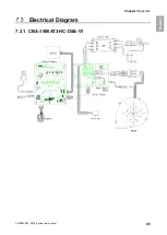
Страница 67: ...Chapter 7Appendix CMN023 005 original instructions 65 English Electrical Diagram 7 3 1 CBA 1500AT3 HC DSA V1...
Страница 69: ...MEMO...

