


チコーエアーテック株式会社
Copyright CHIKO AIRTEC CO., LTD. 2009
9
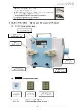
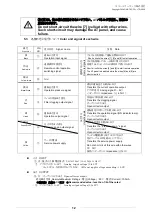
能力レベルスイッチ(
5
段階)
Capacity level
4.5
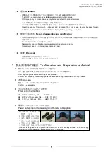
運転手順
Operation procedure
①
設置状態を確認し、電源コンセントを入れてください。
Connect the power plug to the electrical outlet.
②
吸込みホース(フード)を適切な位置にセットします。
Set the suction hose (hood) to a proper position.
③
主電源スイッチを入れて、ランプの点灯を確認してください。
(この状態で、運転モードに入ります)
Turn ON the MAIN POWER switch, and confirm that the power indicator lamp lights.
(
Starts the dust collector
)
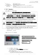
④
AT-
パネルの
ON
スイッチを押して運転を確認して下さい。
Press the ON switch to start the operation.
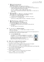
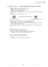
⑤
能力レベルスイッチで任意の能力に設定して下さい。
5
段階の調整となっております。
Choose operation
ability
in five levels. Push Lo-switch or Hi-switch in AT-panel.
Note: The air volume is adjustable in the nonstop method from the low speed to the high speed.
吸込みホースや吐出しホースがふさがれると空気が流れなくなり、
モーター焼けの原因となります。
ホースは、5メートル以下のものをご使用ください。
Clogging the suction hose or discharge hose hinders air flow, and
may stops operation.
Use the hose (length: shorter than 5 meters)
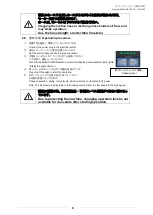
機械の保護の為、運転開始後
4
秒間はレベル変更ができない様になっ
ています。
Due to protecting the machine, changing operation level is not
available for 4 seconds after starting operation.