


チコーエアーテック株式会社
Copyright CHIKO AIRTEC CO., LTD. 2009
7
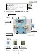
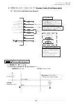
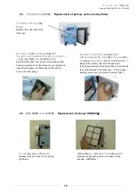
2次フィルタ
:電気部品を粉塵から守ります。
Secondary filter
:
Protecting the circuit and the
electrical parts.
排気
HEPA
フィルタ
:
HEPA
フィルタを装着することによって、クリーンルームクラス
10000
以上
Exhaust
filter
対
応可能です。
:
By mounting the HEPA filter, it becomes available to 10000 clean room class
4
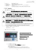
操作
Operation
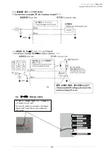
4.1
電源について
Power supply
本機の電源は、直流電源です。
The power supply is DC,
CHV-030AD-HC-V1
:
DC
24V
4.2
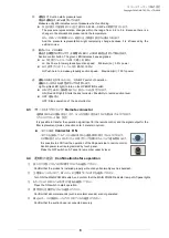
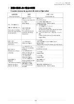
AT
パネルについて
AT panel
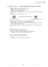
①
フィルタ目詰まり
Filter saturation
フィルタ目詰まりをお知らせする
「
C.F
」と「圧力
表示」が交互に点滅します。
Situation of filter saturation
フィルタが目詰まりして能力が低下した時、パネルにC
.
Fと圧力表示が交互に点滅します。
When a filter performs blocking, and ability decreased, C.F indication turns on a panel.
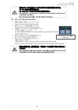
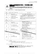
異なった電源で運転されますと、故障の原因になります。
Operating the product with a different power supply may cause a failure.
3
分未満での頻繁な
ON/OFF
操作、特に
30
秒未満で操作をされますと、故障の原因と
なります。必ず
3
分以上のインターバルを置いてから
ON/OFF
の操作をしてください。
It causes the trouble if ON/OFF is frequently operated within 3 minutes, particularly
thereunder 30 seconds. Operate ON/OFF after more than 3 minutes interval.
運転中に主電源の
ON/OFF
操作を行うと、故障の原因となります。誤って運転中に主電源を
切った場合は、
30
秒後に主電源の再投入を行って下さい。
It causes the trouble if ON/OFF is operated by main power supply during operation. In
case of operating OFF by mistake, reclose the main power after 30 seconds.
③能力レベル VOLUME
④運転・ON/OFF
Operation switch
②運転圧力 (kPa)
Suction static pressure level
①フィルタ目詰
FILTER SATURATION