


チコーエアーテック株式会社
Copyright CHIKO AIRTEC CO., LTD. 2009
10
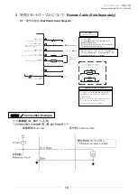
インダクタ(リレー等を付加する場合は
ノイズリミッター(約33Ω+0.1μF)又
はダイオード等を付けて下さい
LOAD
LOAD
1
4
2
3
5
8
7
LOAD
LOAD
GND
DC 1~5V
耐圧 DC 50V
100mmA以下
DC 12V
+側
Service power supply
サービス電源
運転信号
Operation output signal
運転入力信号
Operation input signal
遠隔操作切替信号
Remote-control operation
switching signal
運転圧力信号
Operation pressure signal
フィルタ目詰信号
Filter clogging output signal
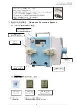
接続例
/
Connection Example
5
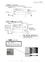
別売リモートケーブルについて
Remote Cable (Sold Separately)
5.1
電気回路図
Electrical circuit diagram
リモート運転
Remote operation switch
リモートモード移行
(ON 時に遠隔操作可能、この時パネル操作は不可)
Shifting to remote mode
(Remote control is possible in the ON, and the panel
is impossible to control at this time.)
②圧力アナログ信号 出力 ≧4.7kΩ ※温度補正なし
Pressure
analog output
:
Output
impedance 4.7kΩ
Temperature correction is not provided.
参照例
Reference
example
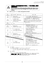
インダクター(リレー等)を付加する場合は出力端子
(端子番号 3・5・6)にノイズリミッター(約 33Ω+0.1μ
F)を付けて下さい
Attach a noise limiter (Approximately 33Ω+0.1μ
F) to the output terminals(Nos.1.2 and 3)
When adding inductors(such as relays)