


チコーエアーテック株式会社
Copyright CHIKO AIRTEC CO., LTD. 2009
12
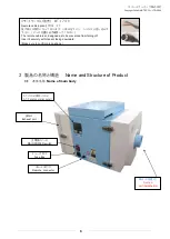
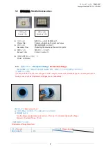
5.2
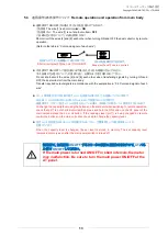
各線の色と信号について
Color and signal of each wire
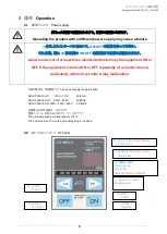
入力
INPUT
:① 接点入力
(無電圧接点
)
Contact input (no-voltage contact)
インピーダンス
Impedance
1.0
k
Ω
出力
OUTPUT
:②~⑥オープンコレクタ
Open collector
耐圧
Voltage resistance 50
V (≦
100 mA
)
入力電圧範囲 :⑦ 電圧入力
0
~
5V
Input voltage range:
⑦
Voltage input of 0 to 5V
インピーダンス
10.0
kΩ ※
+5.0V
以上印加させないでください。
Impedance:10.0k
Ω ※
Do not apply voltage exceeding
+
5.0V.
※誤差が±
4%
ある為、電圧を設定する際は、各レベルの中点の
電圧を印加してください。
※
When setting the voltage,apply a mid-point voltage value for
each level since the error range is
±
4%.
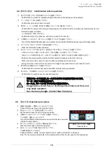
線色
Wire color
PIN
NO.
信号名称
Signal
name
役割
Role
黒
Black
①
運転入力信号
Operation input signal
遠隔信号
(
入力
)
Rem
o
te
s
ig
n
a
ls
④⑧を短絡後、①を短絡して運転を開始します
After short-circuiting pins(4) and(8),short-circuit
pin(1)to start operation.
赤
/
白
Red/white
④
遠隔操作切替信号
Remote-control operation
switching signal
④と⑧を短絡してリモート操作に移行させます
短絡するとタッチパネルの操作はできなくなります
Short-circuits the wires [4] and [8] to start remote operation.
The AT panel is disabled while the wires [4] and [8] are
short-circuited.
黄
Yellow
⑦
能力レベル変更
Change capacity level
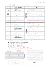
⑦と⑧の間で、
0~5
Vの電圧を印加する事で能力レベル
を変更することが出来ます。
The capacity level can be changed by applying a
voltage of 0 to 5V between pins(7) and(8).
黄
/
白
Yellow /white
⑧
Gnd
黒
/
白
Black/White
②
運転圧力信号
Operation pressure signal
出力信号
O
u
tp
u
t
s
ig
n
a
ls
現在の運転圧力を取り出します
Transfers the current operation output.
アナログ信号
Analog signal
(
1
~
5V
)
インピーダンス
Impedance
(≧
4.7
kΩ)
赤
Red
③
風量不足信号
Air flow shortage
signal
Insufficient airflow signal
風量低下信号を取り出します
Outputs an insufficient airflow signal.
Transfers the
”
Air flow shortage
“ signal
オープンコレクタ出力;
NPN
Open collector output
緑
Green
⑤
運転出力信号
Operation output signal
運転信号(ONランプ)を取り出します
Transfers the operation signal (ON indicator lamp).
オープンコレクタ出力
Open collector output
緑
/
白
Green/White
⑥
圧力不足出力信号
Pressure down output signal
圧力不足信号を取り出します
Transfers the
” pressure down “ signal
オープンコレクタ出力
Open collector output
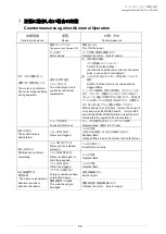
能力レベル
Capacity level
電圧
(DCV)
Voltage(VDC)
1
0.6
~
1.1
2
1.2
~
1.7
3
1.8
~
2.3
4
2.4
~
2.9
5
3.0
~
3.5
6
3.6
~
4.1
7
4.2
~
5.0
電圧
(DC
V)
1
2
3
4
5
6
7
能力レベル
1
0
2
3
4
5
6
7
1
2
3
4
5
6


