background image

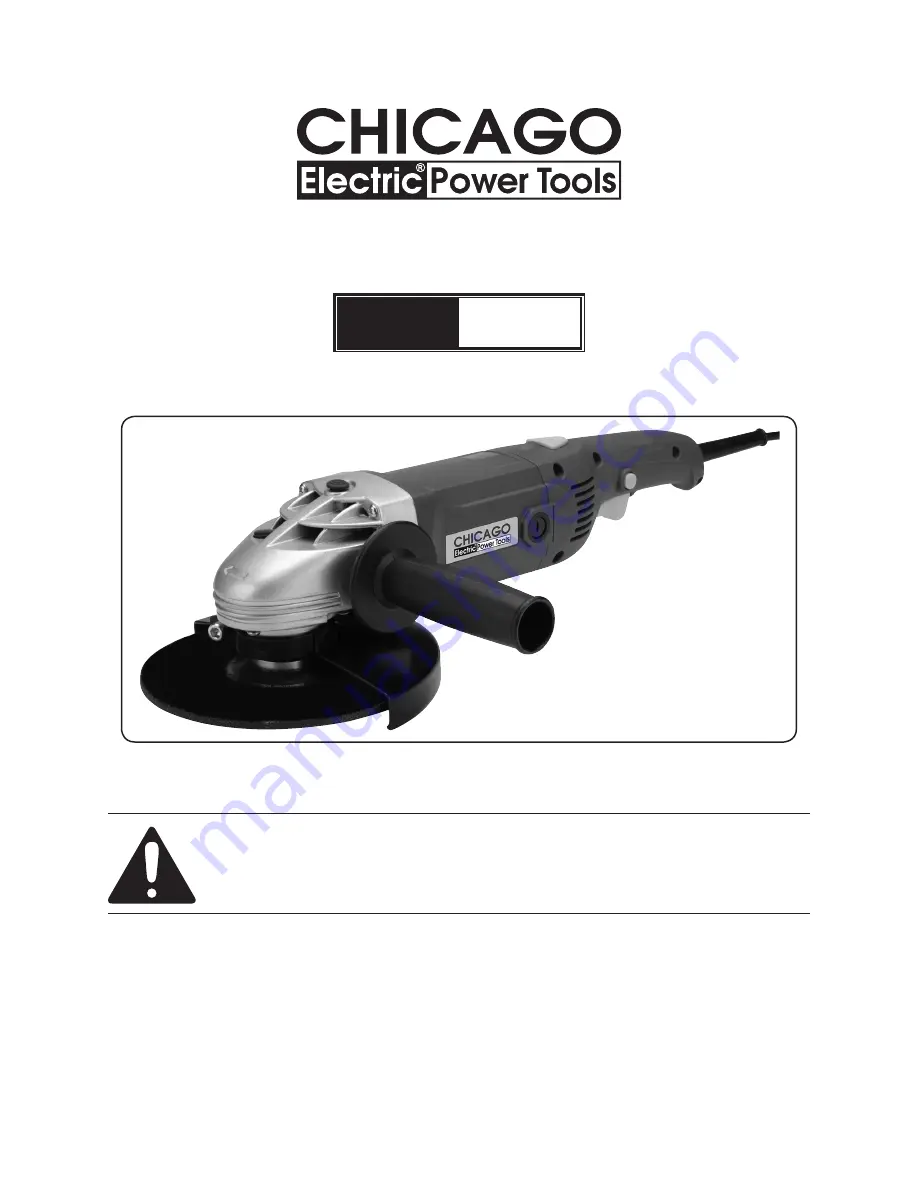
7” Angle grinder

Model

67648

Set up And OperAting inStructiOnS

Visit our website at: http://www.harborfreight.com

 read this material before using this product. 

Failure to do so can result in serious injury. 

SAVe thiS MAnuAl.

Copyright

©

 2010 by Harbor Freight Tools

®

.  All rights reserved.  No portion of this manual or any artwork 

contained herein may be reproduced in any shape or form without the express written consent of Harbor 

Freight Tools.  Diagrams within this manual may not be drawn proportionally.  Due to continuing improvements, 

actual product may differ slightly from the product described herein.

For technical questions or replacement parts, please call 1-800-444-3353.

(Grinding Wheel Sold Separately)           

Содержание 67648

Страница 1: ...r Freight Tools All rights reserved No portion of this manual or any artwork contained herein may be reproduced in any shape or form without the express written consent of Harbor FreightTools Diagramswithinthismanualmaynotbedrawnproportionally Duetocontinuingimprovements actual product may differ slightly from the product described herein For technical questions or replacement parts please call 1 ...

Страница 2: ...g Operations 9 Vibration Safety 9 Grounding 9 Grounded Tools Tools with Three Prong Plugs 10 Double Insulated Tools Tools with Two Prong Plugs 10 Extension Cords 10 Symbology 11 Specifications 12 Unpacking 12 Components 12 Instructions for putting into use 12 Assembly 13 Operating Instructions 14 Tool Set Up 14 Work Piece and Work Area Set Up 15 General Operating Instructions 15 Maintenance And Se...

Страница 3: ...n minor or moderate injury NOTICE is used to address practices not related to personal injury CAUTION without the safety alert symbol is used to address practices not related to personal injury General Power Tool Safety Warnings WARNING Read all safety warnings and instructions Failure to follow the warnings and instructions may result in electric shock fire and or serious injury Save all warnings...

Страница 4: ... before connecting to power source picking up or carrying the tool Carrying power tools with your finger on the switch or energizing power tools that have the switch on invites accidents Remove any adjusting key or wrench d before turning the power tool on A wrench or a key left attached to a rotating part of the power tool may result in personal injury Do not overreach Keep proper e footing and b...

Страница 5: ...shing tool Read all safety warnings instructions illustrations and specifications provided with this power tool Failure to follow all instructions listed below may result in electric shock fire and or serious injury Operations such as polishing or 2 cutting off are not recommended to be performed with this power tool Operations for which the power tool was not designed may create a hazard and caus...

Страница 6: ...ccessory contacting a live wire may make exposed metal parts of the power tool live and shock the operator Position the cord clear of the spinning 11 accessory If you lose control the cord may be cut or snagged and your hand or arm may be pulled into the spinning accessory Never lay the power tool down until 12 the accessory has come to a complete stop The spinning accessory may grab the surface a...

Страница 7: ...cal known to the State of California to cause cancer and birth defects or other reproductive harm Wash hands after handling California Health Safety Code 25249 5 et seq The warnings precautions and 25 instructions discussed in this instruction manual cannot cover all possible conditions and situations that may occur It must be understood by the operator that common sense and caution are factors wh...

Страница 8: ...Contact with a live wire will make exposed metal parts of the tool live and shock the operator Use only wheel types that are 4 recommended for your power tool and the specific guard designed for the selected wheel Wheels for which the power tool was not designed cannot be adequately guarded and are unsafe The guard must be securely attached 5 to the power tool and positioned for maximum safety so ...

Страница 9: ...ould first be examined by a doctor and then have regular medical check ups to ensure medical problems are not being caused or worsened from use Pregnant women or people who have impaired blood circulation to the hand past hand injuries nervous system disorders diabetes or Raynaud s Disease should not use this tool If you feel any medical or physical symptoms related to vibration such as tingling n...

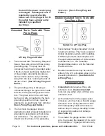
Страница 10: ...e plugged into an 3 appropriate outlet properly installed and grounded in accordance with all codes and ordinances The plug and outlet should look like those in the preceding illustration See 3 Prong Plug and Outlet Double Insulated Tools Tools with Two Prong Plugs Outlets for 2 Prong Plug Tools marked Double Insulated do not 1 require grounding They have a special double insulation system which s...

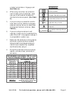
Страница 11: ...nsion cord is properly 7 wired and in good electrical condition Always replace a damaged extension cord or have it repaired by a qualified electrician before using it Protect the extension cords from sharp 8 objects excessive heat and damp or wet areas RECOMMENDED MINIMUM WIRE GAUGE FOR EXTENSION CORDS 120 240 VOLT NAMEPLATE AMPERES at full load EXTENSION CORD LENGTH 25 50 75 100 150 0 2 0 18 18 1...

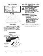
Страница 12: ...n please call Harbor Freight Tools at 1 800 444 3353 as soon as possible Components Figure 1 Spanner 53 Wheel Guard 3 Lock on Switch 46 Trigger 47 Hex Wrench 55 Auxiliary Handle 23 Handle 43 Carbon Brush Cap 41 Spindle Lock Button 21 Grinding Wheel Sold Separately Instructions for putting into use Read the entire Important Safety Information section at the beginning of this manual including all te...

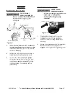
Страница 13: ...uard as needed to 2 shield you during the planned work Use the Hex Wrench 55 to tighten 3 the Socket Head Bolt securely Check the Wheel Guard to ensure it is firmly in place Adjust if necessary before proceeding Installing the Auxiliary Handle TO PREVENT SERIOUS INJURY Do not operate this tool with one hand only or without the Auxiliary Handle properly installed Figure 2 Auxiliary Handle locations...

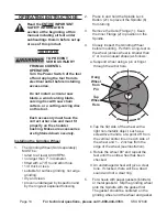
Страница 14: ...ng dry and clean proven undamaged by inspection and by the ring test explained following Press in and hold the Spindle Lock 2 Button 21 to prevent the Spindle 6 from turning Remove the Outer Flange 1 Keep 3 the Inner Flange 2 in position on the Spindle Closely inspect the Grinding Wheel 4 before mounting Perform a ring test on the wheel unless wheel is smaller than 4 or is an unusual shape as foll...

Страница 15: ... working You must use personal safety equipment 5 including but not limited to ANSI approved eye and hearing protection as well as heavy work gloves Before beginning work provide for 6 sparks and debris that will fly off the work surface General Operating Instructions To prevent serious injury Grip the tool firmly in both hands Press and release the Trigger to make 1 sure the Trigger is not locked...

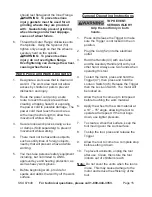
Страница 16: ...oose screws misalignment or binding of moving parts cracked or broken parts damaged electrical wiring and any other condition that may affect its safe operation Periodically blow dust and grit out of 2 the motor vents using dry compressed air Always wear ANSI approved safety goggles and NIOSH approved breathing protection when performing this maintenance operation After Use 3 wipe external surface...

Страница 17: ... is worn down by more than 1 3 replace both carbon brushes To clean old carbon brushes before 4 reusing them rub the contact areas with a pencil eraser Hold the spring clips to the side and 5 carefully without forcing them reinsert the old carbon brushes in the same orientation to reduce wear When installing the carbon brushes 6 make sure the carbon portions of the carbon brushes contact the motor...

Страница 18: ...s Excessive noise or rattling Internal damage or wear Carbon brushes or bearings for example Have qualified technician service tool Overheating Forcing tool to work too fast 1 Blocked motor housing vents 2 Motor being strained by long or small 3 diameter extension cord Allow tool to work at its own rate 1 Wear ANSI approved safety goggles and 2 NIOSH approved dust mask respirator while blowing dus...

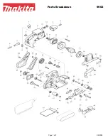
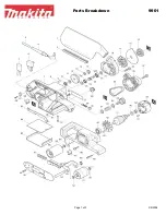
Страница 19: ...lder 2 40 Carbon Brush 2 41 Brush Holder Cap 2 42 Plastic Plate 1 43 Handle 1 44 Cord Clamp 1 46 Switch 1 47 Trigger 1 48 Handle Cover 1 49 Tapping Screw ST4 x 16C 6 50 Tapping Screw ST4 x 14F 1 51 Cord Sleeve 1 52 Cord 1 53 Spanner 1 54 Rubber Cap 3 55 Hex Wrench 1 PLEASE READ THE FOLLOWING CAREFULLY The manufacturer and or distributor has provided the parts list and assembly diagram in this manu...

Страница 20: ...U 67648 ASSEMBLY DIAGRAM Record Product s Serial Number Here Note If product has no serial number record month and year of purchase instead Note Some parts are listed and shown for illustration purposes only and are not available individually as replacement parts ...

Страница 21: ...ncidental or consequential damages so the above limitation of exclusion may not apply to you This warranty is expressly in lieu of all other warranties express or implied including the warranties of merchantability and fitness To take advantage of this warranty the product or part must be returned to us with transportation charges prepaid Proof of purchase date and an explanation of the complaint ...

Отзывы: