6 K - 2 E N G I N E C O O L I N G
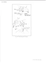
Fig. 3—Water Pump—Typical V-8
THEORY OF OPERATION
The engine cooling system is designed to maintain the
tfngine at its most efficient operating temperature at all
engine speeds and all driving conditions. During
combustion of the air-fuel mixture, combustion gas
temperatures may be as high as 4500 degrees. The
cylinder walls, cylinder heads and pistons absorb some
but not all of the heat. They, in turn, must be provided
with some means of cooling to prevent permanent
damage. Temperatures higher than the limit imposed by
the oil properties will destroy the lubricating characteris
tics of the oil and lead to subsequent engine failure. It is
desirable to operate the engine at a temperature as close
as possible to the limit imposed by the oil properties.
Removing too much heat would lower the thermal
efficiency; therefore, the cooling system functions to
remove approximately 35 percent of the heat produced
during combustion.
COOLING SYSTEM CIRCULATION
Six-Cylinder Engine
The water pump discharges coolant into the water jacket
chamber between the front face of the block and the
number one cylinder (Fig. 4). Coolant then flows through
the block, toward the rear, passing through two large cast
openings into the cylinder head, to cool the valve seats,
and forward to the water outlet at the front of the head.
Some coolant is directed through a small hole in the
cylinder head gasket to an area around each spark plug.
During engine warm-up, when the thermostat is closed,
coolant is redirected to the water pump through a
coolant by-pass in the cylinder head and block. Coolant
circulation, after normal operating temperatures are
reached (thermostat open), flows through the coolant
outlet and the pellet-type thermostat to the radiator.
Eight-Cylinder Engine
The water pump discharges coolant to each bank of
cylinders. The coolant flow is from the front of each
bank around each cylinder and toward the rear of the
block. Large passages connecting the block to cylinder
head directs coolant over and around the alternately
spaced inlet and exhaust ports, as well as around the
exposed exhaust valve guide inserts. Smaller circular
holes permit metered amounts of coolant to pass from
the cylinder block to cored passages surrounding the
spark plugs.
On “Small V8” engines during warm up (thermostat
closed), coolant is redirected, through a small passage
located in the front of the right cylinder head and block
to a mating hole in the extreme lower portion of the
water pump runner.
On “Mark IV” engines during warm up (thermostat
closed), coolant is redirected to the water pump by way
of a recirculating passage in the intake manifold which
is connected externally to the pump body.
Coolant circulation after normal operating temperatures
are obtained (thermostat open), is directed from the
intake manifold through the coolant outlet and
thermostat to the radiator.
LIGHT DUTY TRUCK SERVICE MANUAL
Содержание Light Duty Truck 1973
Страница 1: ......
Страница 4: ......
Страница 6: ......
Страница 39: ...HEATER AND AIR CONDITIONING 1A 13 Fig 14 Heater Wiring Diagrams LIGHT DUTY TRUCK SERVICE MANUAL...
Страница 53: ...HEATER AND AIR CONDITIONING 1A 27 LIGHT DUTY TRUCK SERVICE MANUAL...
Страница 115: ...LIGHT DUTY TRUCK SERVICE M A N U A L HEATER AND AIR CONDITIONING 1A 89...
Страница 123: ...BODY 1B 3 Fig 6 Typical 06 Van LIGHT DUTY TRUCK SERVICE MANUAL...
Страница 149: ...BODY 1B 29 Fig 84 Body Mounting 06 Fig 85 Body Mounting 14 LIGHT DUTY TRUCK SERVICE MANUAL...
Страница 171: ...LIGHT DUTY TRUCK SERVICE M A N U A L Fig 2 Frame Horizontal Checking Typical FRAME 2 3...
Страница 173: ...LIGHT DUTY TRUCK SERVICE M A N U A L Fig 4 10 30 Series Truck Frame FRAME 2 5...
Страница 174: ...2 6 FRAME LIGHT DUTY TRUCK SERVICE MANUAL Fig 5 Underbody Reference Points G Van...
Страница 177: ...LIGHT DUTY TRUCK SERVICE MANUAL G 10 20 C 10 P 10 30 Fig 2 Front Suspension C P K Typical FRONT SUSPENSION 3 3...
Страница 185: ...FRONT SUSPENSION 3 11 Fig 16 Toe out on Turns LIGHT DUTY TRUCK SERVICE MANUAL...
Страница 224: ......
Страница 229: ...REAR SUSPENSION AND DRIVELINE 4 5 Fig 13 Rear Spring Installation C K Models LIGHT DUTY TRUCK SERVICE MANUAL...
Страница 266: ......
Страница 310: ...5 44 BRAKES C MODELS G MODELS P MODELS Fig 77 Parking Brake System LIGHT DUTY TRUCK SERVICE MANUAL...
Страница 351: ...ENGINE 6 15 Fig ID Sectional View of Eight Cylinder Engine LIGHT DUTY TRUCK SERVICE MANUAL...
Страница 375: ...EN G IN E 6 39 LIGHT DUTY TRUCK SERVICE MANUAL...
Страница 376: ...6 4 0 ENGINE LIGHT DUTY TRUCK SERVICE MANUAL...
Страница 377: ...ENG IN E 6 41 LIGHT DUTY TRUCK SERVICE MANUAL...
Страница 378: ...LIGHT DUTY TRUCK SERVICE MANUAL Fig 37L K Series Engine Front Mount 6 42 ENG INE...
Страница 379: ...E N G IN E 6 43 FRONT MOUNT REAR MOUNT Fig 38L G Series Engine Mounts LIGHT DUTY TRUCK SERVICE MANUAL...
Страница 400: ...6 6 4 ENG INE LIGHT DUTY TRUCK SERVICE MANUAL...
Страница 401: ...ENG IN E 6 65 LIGHT DUTY TRUCK SERVICE MANUAL...
Страница 402: ...6 6 6 ENGINE LIGHT DUTY TRUCK SERVICE MANUAL...
Страница 403: ...E NG IN E 6 67 Fig 36V C Series Engine Mounts LIGHT DUTY TRUCK SERVICE MANUAL...
Страница 410: ......
Страница 423: ...EN G IN E C OOLING 6K 13 Fig 16 Overheating Chart LIGHT DUTY TRUCK SERVICE MANUAL...
Страница 424: ...6 K 1 4 ENG INE COOLING Fig 17 Coolant Loss Chart LIGHT DUTY TRUCK SERVICE MANUAL...
Страница 455: ...ENGINE FUEL 6M 31 Fig K13 Accelerator Controls P30 42 454 Engine LIGHT DUTY TRUCK SERVICE MANUAL...
Страница 456: ...6M 32 ENGINE FUEL Fig K15 Accelerator Controls G Van L 6 LIGHT DUTY TRUCK SERVICE MANUAL...
Страница 492: ......
Страница 506: ...CEC PLUNGER IS EXTENDED Fig lid Vacuum Advance Diagram Six Cylinder Engine 6T 14 EMISSION CONTROL SYSTEMS...
Страница 512: ...Fig 18e Vacuum Advance Diagram V8 Engine...
Страница 515: ...EMISSION CONTROL SYSTEMS 6T 23 Fig If Six Cylinder A I R System LIGHT DUTY TRUCK SERVICE MANUAL...
Страница 516: ...6 T 2 4 E M IS S IO N CONTROL SYSTEMS LIGHT DUTY TRUCK SERVICE MANUAL...
Страница 517: ...E M IS S IO N C O N TR O L SYSTEM S 6T 25 Fig 4f Diverter Valve Vent Valve LIGHT DUTY TRUCK SERVICE MANUAL...
Страница 528: ......
Страница 540: ...6 Y 1 2 ENGINE ELECTRICAL Fig 16b Battery Installation C K Series LIGHT DUTY TRUCK SERVICE MANUAL...
Страница 572: ...6Y 44 ENGINE ELECTRICAL Fig 25i V 8 Spark Plug Wire Installation LIGHT DUTY TRUCK SERVICE MANUAL...
Страница 590: ......
Страница 592: ...7M 2 CLUTCHES MANUAL TRANSMISSIONS VIEW B Fig la Clutch Linkage Assy C K Models LIGHT DUTY TRUCK SERVICE MANUAL...
Страница 593: ...CLUTCHES MANUAL TRANSMISSIONS 7M 3 LIGHT DUTY TRUCK SERVICE MANUAL...
Страница 594: ...7M 4 CLUTCHES MANUAL TRANSMISSIONS Fig lc Clutch Linkage Assy P Models LIGHT DUTY TRUCK SERVICE MANUAL...
Страница 598: ...7M 8 CLUTCHES MANUAL TRANSMISSIONS LIGHT DUTY TRUCK SERVICE MANUAL...
Страница 642: ......
Страница 654: ......
Страница 656: ...LIGHT DUTY TRUCK SERVICE MANUAL Fig 19M Drive Range Low First Gear Typical 7A 14 AUTOMATIC T R A N S M IS S IO N...
Страница 662: ...LIGHT DUTY TRUCK SERVICE M A N U A L Fig 22M LI Range Manual First Gear Typical 7A 20 AUTOMATIC TRANSMISSION...
Страница 668: ...LIGHT DUTY TRUCK SERVICE M A N U A L Fig 25M Reverse Range Typical 7A 26 AUTOMATIC T R A N S M IS S IO N...
Страница 739: ...FUEL TANKS AND EXHAUST 8 9 Fig 15 Filler Neck and Vent Hose Van LIGHT DUTY TRUCK SERVICE MANUAL...
Страница 740: ...8 10 FUEL TANKS AND EXHAUST Fig 16 Fuel Feed and Return Pipes Front C K LIGHT DUTY TRUCK SERVICE MANUAL...
Страница 743: ...FUEL TANKS AND EXHAUST 8 13 LIGHT DUTY TRUCK SERVICE MANUAL...
Страница 744: ...8 14 FUEL TANKS AND EXHAUST LIGHT DUTY TRUCK SERVICE MANUAL...
Страница 746: ...8 16 FUEL TANKS AND EXHAUST Fig 2 5 Fuel Feed Pipe Front P 105 4 2 LIGHT DUTY TRUCK SERVICE MANUAL...
Страница 760: ...8 30 FUEL TANKS AND EXHAUST Fig 40 Exhaust Pipe P Models LIGHT DUTY TRUCK SERVICE MANUAL...
Страница 761: ...FUEL TANKS AND EXHAUST 8 31 LIGHT DUTY TRUCK SERVICE MANUAL...
Страница 763: ...FUEL TANKS AND EXHAUST 8 33 LIGHT DUTY TRUCK SERVICE MANUAL...
Страница 766: ......
Страница 781: ...STEERING 9 15 OIL PRESSURE OIL RETURN PORT VALVE BODY Fig 21 Left Turn Position LIGHT DUTY TRUCK SERVICE MANUAL...
Страница 832: ...LIGHT DUTY TRUCK SERVICE MANUAL Fig 106 Power Steering Pump Mounting Typical 9 66 STEERING...
Страница 833: ...PUMP ASSEMBLY STEERING GEAR TYPICAL SMALL V8 TYPICAL LARGE V8 STEERING 9 67...
Страница 860: ...9 94 STEERING LEAKAGE AREAS Fig 133 Power Steering Gear Leakage LIGHT DUTY TRUCK SERVICE MANUAL...
Страница 861: ...STEERING 9 95 Fig 134 Power Steering Pump Leakage LIGHT DUTY TRUCK SERVICE MANUAL...
Страница 864: ......
Страница 876: ......
Страница 886: ...11 10 CHASSIS SHEET METAL LIGHT DUTY TRUCK SERVICE MANUAL...
Страница 891: ...ELECTRICAL BODY AND CHASSIS 12 5 LIGHT DUTY TRUCK SERVICE MANUAL...
Страница 897: ...ELECTRICAL BODY AND CHASSIS 12 11 Fig 14 Instrum ent Cluster Assembly C K Models LIGHT DUTY TRUCK SERVICE MANUAL...
Страница 934: ......
Страница 942: ......
Страница 970: ......
Страница 972: ......
Страница 974: ......
Страница 976: ...V...
Страница 978: ......
Страница 979: ......


