S e c . 7B
P a g e 46
T RA N SM ISSIO N ON-VEHICLE SERVICE
NOTE: Pull secondary w ire out of center
so ck et in the distributor cap and ground w ire to
prevent p o ssib le dam age to co il.
2. P o sitio n s e le c to r le v e r in "N" (Neutral).
Turn ignition sw itch to "START" position. Engine
should sta rt but v eh icle must not m ove. Turn ig
nition sw itch to "OFF."
3. P o sitio n s e le c to r le v e r in "R" (R everse).
Turn ignition sw itch to "START" position. Engine
m ust not sta rt.
4. Move s e le c to r le v e r to "D" (Drive) p o s i
tion. Engine m ust not sta rt.
5. If the previou s conditions are not met for
the neutral sa fety and back-up lamp switch,adjust
the sw iv el p osition on rod (H) until operation is as
stated in Steps 2 -4 .
DOWNSHIFT SWITCH ADJUSTMENT
NOTE: The downshift sw itch mounted at the
carburetor is activated by the carburetor throttle
le v e r . When the throttle le v e r rea ch es wide open
p o sitio n it r e su lts in a forced downshift to the
tr a n sm issio n u n less veh icle is in "LI."
1. Move carburetor throttle le v e r to wide
open p osition .
2. L oosen two adjusting sc r e w s (at slotted
holes) on sw itch bracket.
3. P o sitio n sw itch and bracket a ssem b ly so
that clea ra n ce betw een throttle le v e r and sw itch
plunger (fully d ep ressed ) is .05-in ch .
4. Tighten the two adjusting s c r e w s to 20-30
inch-pounds torque.
5. Road te st and check for proper operation.
SECTION 7B
On-Velude Sendee. Op&uuUo-HA,
AT475 T RA N SM ISSIO N
REPLACEMENT
The follow ing p roced u res apply to veh icles
covered by this supplem ent. H owever, it may be
n e c e ssa r y to rem ove air tanks, fuel tanks, special
equipm ent, e tc ., on som e v eh icles to provide
cle a ra n ce b efore the tra n sm issio n is rem oved.
Overhaul inform ation for the AT475 tra n s
m is s io n is contained in 40-6 0 S e r ie s Truck Chas
s i s O verhaul Manual Supplem ent S T -334-72.
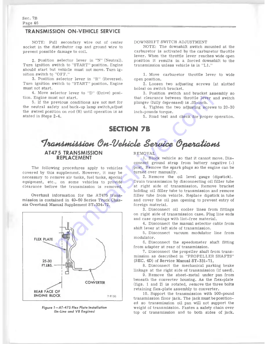
Figure l - A T - 4 7 5 Flex Plate Installation
(In-Line an d V8 Engines)
REMOVAL
1. B lock v eh ic le so that it cannot m ove. D is
connect ground strap from battery negative (-)
p o st. R em ove the spark plugs so the engine can be
turned over m anually.
2. R em ove the o il le v e l gauge (dipstick).
D rain tr a n sm issio n by disconnecting o il f ille r tube
at right sid e of tra n sm issio n . R em ove bracket
holding o il fille r tube to tr a n sm issio n and rem ove
fille r tube from v e h ic le . R eplace dipstick in tube
and cover the o il pan opening to prevent entry of
foreign m aterial.
3. D iscon n ect o il c o o ler lin es from fittin gs
on right sid e of tr a n sm issio n c a se . Plug lin e ends
and c a se openings with lin t-fr e e m aterial.
4. D iscon n ect the manual se le c to r cable from
shift le v e r at left sid e of tr a n sm issio n .
5. D isconnect vacuum modulator lin e from
m odulator.
6. D iscon n ect the sp eed om eter shaft fitting
from adapter at rear of tr a n sm issio n .
7. D iscon n ect the p ro p eller shaft from tra n s
m issio n as d escrib ed in "PROPELLER SHAFTS"
(SEC. 4D) of S erv ice Manual S T -331-71.
8. D iscon n ect the m echanical parking brake
linkage at the right sid e of tr a n sm issio n (if used).
9. Rem ove the sh e e t-m e ta l under pan from
beneath the con verter housing. A s the flex -p la te
(fig s. 1 and 2) is rotated, rem ove the three bolts
retaining fle x -p la te a ssem b ly to con verter.
10. Support the tr a n sm issio n with 500-pound
tr a n sm issio n floor jack. The jack m ust be p o sitio n
ed so tr a n sm issio n o il pan w ill not support the
w eight of tr a n sm issio n . F asten a safety chain over
top of tr a n sm issio n and to both sid e s of jack.


